Encoder-disc terminology
1 Vpp Sine/Cosine Signals: Definitions of Amplitude, Offset and Termination
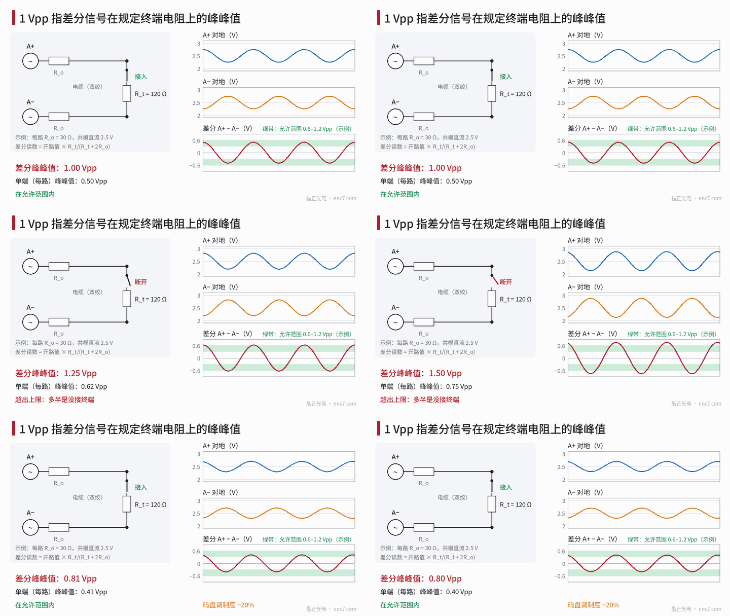
“1 Vpp” means the peak-to-peak value of the differential signal across the specified termination resistance (commonly 120 Ω). This article derives the source-impedance / termination divider: with 30 Ω output resistance per side the open-circuit reading is 1.5 Vpp; it explains single-ended versus differential measurement, how disc modulation depth enters the amplitude tolerance multiplicatively, and lists common measurement mistakes with corrections.
Incoming inspection measures 1.45 Vpp on an oscilloscope and rejects the part as “above the 1.2 Vpp upper limit”; the same readhead on a drive reads 0.97 Vpp. Neither instrument is wrong—they are not measuring the same quantity. Behind the apparently simple figure “1 Vpp” sit four premises—differential, peak-to-peak, termination resistance and measurement bandwidth—and missing any one of them can shift the reading by tens of percent.
Definition: differential, peak-to-peak, termination
Each channel of a sine/cosine analogue interface has two wires A+ and A−, complementary and each riding on a common-mode DC level (for example 2.5 V, illustrative). “1 Vpp” means:
- Differential: A = (A+) − (A−), not the voltage of either wire to ground;
- Peak-to-peak: the peak-to-peak of the differential sine; the peak amplitude is 0.5 V and the Lissajous-circle diameter is 1 V;
- Termination: the receiver places the specified resistance R_t across A+ and A−, commonly 120 Ω, close to the characteristic impedance of twisted pair;
- Low speed: the signal frequency is well below the bandwidth of the readhead front end and the cable; amplitude droop allowed at high frequency is specified separately.
The AC component of each single-ended line is only 0.5 Vpp. Data sheets usually also give the allowed amplitude range (for example 0.6–1.2 Vpp, illustrative), offset, A/B amplitude ratio and phase-difference requirements, and the amplitude drop at the highest frequency; these values vary by product and should be written into the technical agreement. Offset must use the peak amplitude 0.5 V as denominator; the basis issue is covered in the DC-offset article of this library.
Source impedance and the termination divider
Model each output as a voltage source in series with output resistance R_o, open-circuit differential voltage V_oc, and a receiver load of R_t in parallel with the receiver differential input resistance R_in, plus a round-trip cable resistance R_c:
V_read = V_oc · R_L / (R_L + 2R_o + R_c), R_L = R_t ∥ R_in
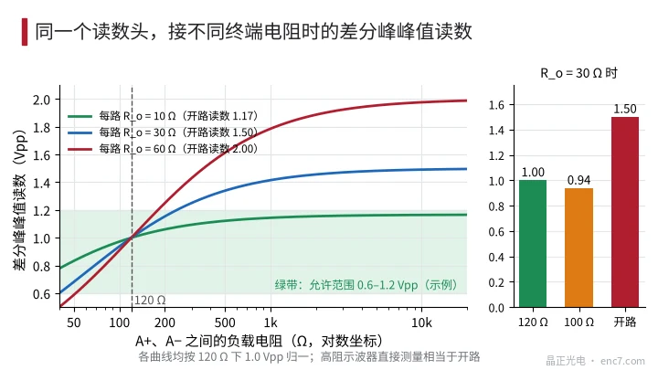
Without termination the reading is V_oc, and its ratio to the 120 Ω reading is (R_t + 2R_o)/R_t:
| Per-side R_o | Open / 120 Ω | At 100 Ω instead | From R_t ±5% |
|---|---|---|---|
| 10 Ω | 1.17 | −2.8% | ±0.7% |
| 30 Ω | 1.50 | −6.3% | ±1.7% |
| 60 Ω | 2.00 | −9.1% | ±2.5% |
Assuming 0.13 Ω/m per conductor, a 20 m cable contributes 5.2 Ω round-trip and, at R_o = 30 Ω, lowers the amplitude by a further ≈2.8%; a receiver differential input of 10 kΩ (assumed) lowers it by only ≈0.4%.
Output resistance can be recovered from two measurements: open reading V_open and terminated reading V_term give
R_o = (R_t / 2) · (V_open / V_term − 1)
For example 1.45 and 0.97 Vpp at R_t = 120 Ω yield R_o ≈ 30 Ω. High-Z oscilloscope readings can then be converted to the specified termination (see Figure 2).
Single-ended versus differential measurement
Differential measurement has three practical forms: a differential probe; two probes of the same type on A+ and A− with the scope computing A − B; or the differential-amplifier output of the receiver itself. The second is the most common and the easiest to get wrong. When the two channel gains differ by k, common-mode voltage leaks into the differential by the factor k: at k = 2% and a common-mode DC of 2.5 V that produces a false offset of 50 mV, equal to 10% of the peak amplitude, and common-mode noise leaks in with it. Both channels must therefore use the same attenuation, DC coupling, and a gain flatness check on the same signal before the measurement.
Do not clip the scope ground lead onto A−: A− is then shorted to earth through the scope ground, the driver is forced to source a large current, the waveform distorts, and in severe cases the part is damaged.
Measuring only A+ and multiplying by 2 assumes that A+ and A− are perfectly complementary. Even-harmonic content, offset and amplitude asymmetry of the single-ended waveforms are partly cancelled in the differential, so single-ended ×2 can overestimate or underestimate.
Peak-to-peak itself is also affected by noise. Reading the max/min of a noisy waveform directly is high; average over many periods, or take the fundamental amplitude a_1 from an FFT and report 2a_1 as peak-to-peak.
How disc modulation depth enters the 1 Vpp tolerance
If the readhead uses an intensity closed loop that holds the mean photocurrent at a fixed value, the differential amplitude is proportional to the modulation depth M (differential peak-to-peak = 4M·D, with D the single-ended DC; see the modulation-depth article of this library). When disc modulation depth falls from 0.60 to 0.51 (−15%), 1.00 Vpp becomes 0.85 Vpp. Without intensity closed loop the amplitude also tracks the disc’s average transmittance.
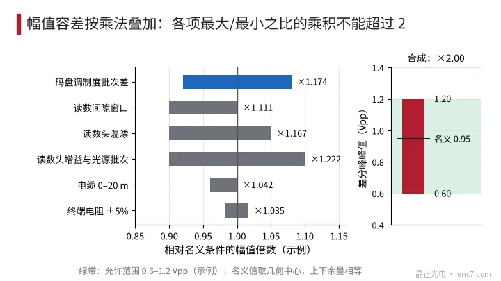
Every contribution is multiplicative, so the budget must multiply “max/min ratios”. An allowed range of 0.6–1.2 Vpp has a ratio of 2; the product of all factor ratios must not exceed 2. Example (see Figure 3): disc modulation-depth lot spread ±8% (×1.174), gap window ×1.111, readhead temperature drift ×1.167, readhead gain and source lot ±10% (×1.222), cable ×1.042, termination resistance ×1.035; the product is 2.00 and exactly fills the budget. The nominal amplitude should then be taken at the geometric centre, about 0.95 Vpp, not at 1.0 Vpp, so that both limits stay inside the range. If disc modulation depth is relaxed to ±15% (×1.35), the product of the remaining factors may be only about 1.48.
Common measurement mistakes
| Mistake | Reading bias (example) | Correct practice |
|---|---|---|
| High-Z scope direct, no termination | +50% at R_o = 30 Ω | Bridge the specified R_t, or convert via R_o |
| 100 Ω used instead of 120 Ω | −6.3% at R_o = 30 Ω | Use the agreed value and include R_in |
| Single-ended ×2 only | Direction depends on asymmetry | Measure differentially |
| Two-channel subtract with mismatched gain | 2% mismatch → ≈50 mV false offset | Same probe type, DC coupled, flatten first |
| Max/min of a noisy waveform | High, noise-dependent | Multi-period average or FFT fundamental |
| Measurement at high speed | Front-end bandwidth droop, low | Measure amplitude at the specified low speed |
| Treating 1 Vpp as peak | Offset ratio wrong by a factor of two | Peak amplitude is 0.5 V |
Engineering points
- Write the full specification: differential peak-to-peak, termination resistance, receiver input impedance, measurement speed or frequency; missing any one makes the number incomparable.
- Recover R_o from open and terminated readings, R_o = (R_t/2)·(V_open/V_term − 1), so that different measurement conditions can be converted.
- When subtracting two channels for a differential measurement, use matched probes, DC coupling and a gain flatness check first; at 2.5 V common mode a 2% mismatch is already a 50 mV false offset.
- Budget amplitude tolerance multiplicatively; the total ratio of 0.6–1.2 Vpp is 2, and disc modulation-depth lot spread must be allocated from that ratio.
- Take the nominal amplitude at the geometric centre of the allowed range under the multiplicative deviations, not mechanically at 1.0 Vpp.
- Measure offset, amplitude ratio and phase requirements under the same termination; use 0.5 V peak amplitude as the offset denominator.
Summary
“1 Vpp” is the peak-to-peak of the differential signal across the specified termination at low speed; each single-ended line carries only 0.5 Vpp. The divider formed by output resistance and termination can make the open reading half again, or even twice, the specified value. Disc modulation-depth lot spread enters the amplitude budget multiplicatively and, together with the other factors, shares the factor-of-2 ratio between 0.6 and 1.2 Vpp. Write the measurement conditions clearly and measure differentially into the termination, and the supplier’s and customer’s readings will agree.
Translated from the ENC7 Chinese technical library (article 0266). Read the Chinese original. Need a disc built to your drawing? Request a quote or see our custom encoder discs.
© Langfang Jingzheng Optoelectronic Technology Co., Ltd. All rights reserved. This article was created with AI assistance.