Industry applications in depth
23-bit encoders at 6000 rpm: choosing line count and interpolation
Aimed at 6000 rpm and 23-bit singleturn resolution, this article compares line-count and interpolation pairings such as 1024×8192, 2048×4096 and 4096×2048, calculates signal frequency, front-end bandwidth, signal-to-noise ratio and ADC bits, pitch and read gap, and points out the timing-error constraint that follows when 1 count lasts only 1.19 ns.
A 23-bit singleturn encoder produces 2²³ = 8 388 608 counts per revolution, or 0.154″ per count. That product can be split as 1024 lines with an interpolation factor of 8192, or as 2048×4096 or 4096×2048. The resolution is identical, yet the demands on the encoder disc, the front end and the ADC differ widely. Taking a rated speed of 6000 rpm as the working condition, this article works through the requirements of each split and points out which constraints do not depend on line count.
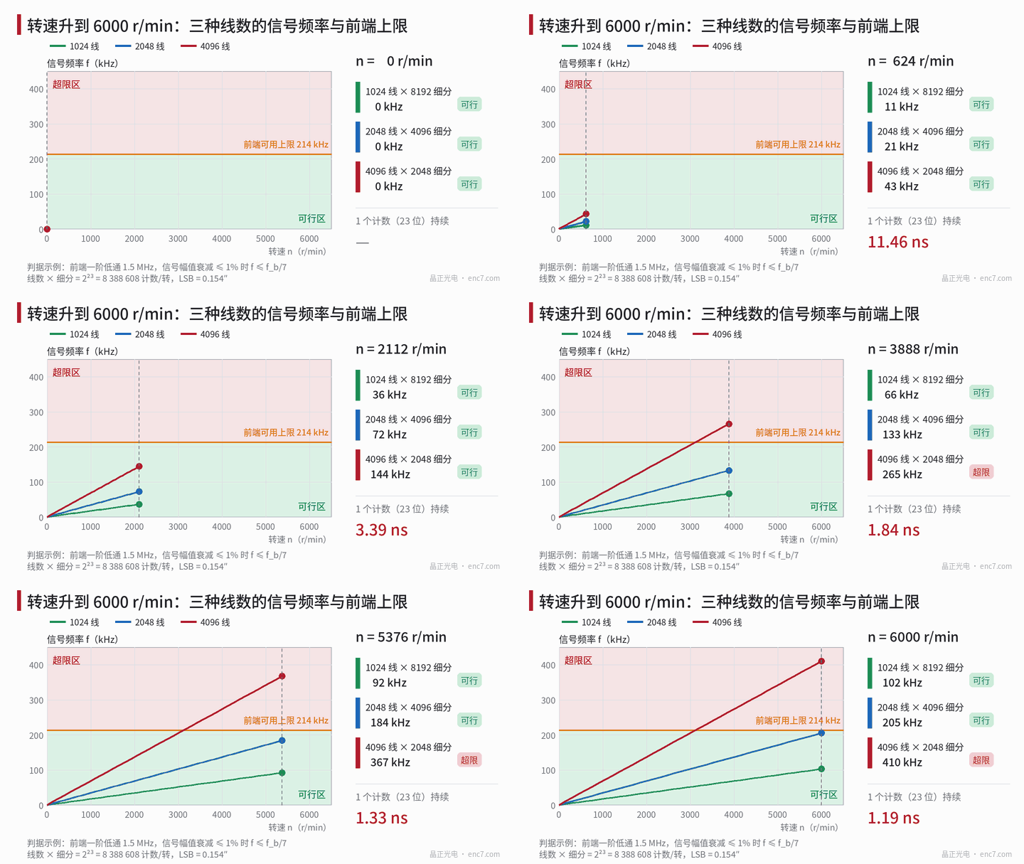
Convert first: how long is one count
6000 rpm is 100 r/s, so ω = 628.3 rad/s. The duration of one count is
t_LSB = 60 / (n·2²³) = 1.19 ns
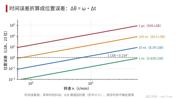
where n is the rotational speed (r/min). Position error and time error therefore obey Δθ = ω·Δt: 1 ns corresponds to 0.84 LSB, and 10 ns to 8.4 LSB (see Figure 3).
On the other hand, the LSB is only resolution, not accuracy. At a read radius of 12 mm, 1 μm of eccentricity is already 17.2″, about 111 LSB. 23 bits is first of all an indicator of noise and speed smoothness; absolute accuracy is still set by eccentricity, graduation error and interpolation error.
Constraints that depend on line count
Signal frequency: f = N·n/60. At 6000 rpm, 1024, 2048 and 4096 lines give 102, 205 and 410 kHz respectively. Approximating the front end as a first-order low-pass, 1% amplitude attenuation requires f/f_b = 0.1425 (a phase lag of 8.1°), i.e. f_b ≈ 7f.
Signal-to-noise ratio: Let the RMS noise be s times the signal amplitude. It produces a phase jitter of s rad on the Lissajous circle, which converts to a mechanical angle σ_θ = s·θ_p/2π, where θ_p = 360°/N is one signal period. Imposing σ_θ ≤ 1 LSB gives s ≤ LSB·2π/θ_p. Doubling the line count halves θ_p, doubles the allowed s, and relaxes the SNR requirement by 6 dB. If ADC noise accounts for only 1/4 of the total noise power, then when the signal fills the full scale the effective number of bits satisfies ENOB ≥ (SNR + 6 − 1.76)/6.02.
Interpolation error: For the same signal defect, the mechanical-angle error is proportional to θ_p. A 1% DC offset gives an error of 0.01·θ_p/2π.
| Line count × interpolation | Frequency at 6000 rpm | Front-end f_b (attenuation ≤1%) | SNR required for σ≤1 LSB | ADC effective bits (approx.) | Error from a 1% offset |
|---|---|---|---|---|---|
| 1024×8192 | 102 kHz | 0.72 MHz | 62 dB | 11 | 2.01″ |
| 2048×4096 | 205 kHz | 1.44 MHz | 56 dB | 10 | 1.01″ |
| 4096×2048 | 410 kHz | 2.87 MHz | 50 dB | 9 | 0.50″ |
| 8192×1024 | 819 kHz | 5.75 MHz | 44 dB | 8 | 0.25″ |
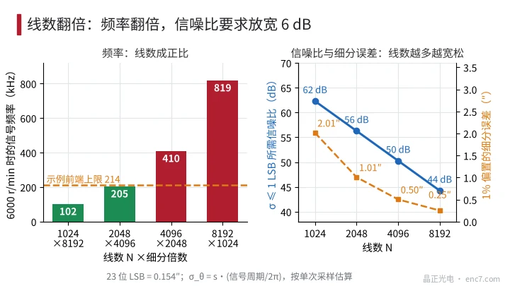
The SNR figure is the requirement for a single sample at maximum speed; at low speed it can be relaxed by averaging multiple samples. If the ADC unfolds the phase by sample-by-sample conversion, the phase increment between adjacent points must be less than π, so f_s must be at least 2f_max, and a practical choice is a factor of 4: about 0.8 MSPS at 2048 lines and about 1.6 MSPS at 4096 lines.
A constraint independent of line count: time
After the incremental signals have been amplified by the front end, the delay between the two channels A and B sets the dynamic error at high speed. Take a first-order low-pass front end with f_b = 1.5 MHz; the group delay is 1/(2πf_b) = 106 ns.
- Common delay τ: the position lag is ω·τ = 13.8″, about 89 LSB, and can be compensated from speed in the steady state.
- Differential delay Δτ: the A/B phase difference departs from 90°, producing an error 2 times per signal period with amplitude ω·Δτ/2. When the two channel bandwidths differ by 5%, Δτ = 5.3 ns, the error is 0.34″, about 2.2 LSB.
Both terms depend only on ω and on delay, not on line count: raising the line count multiplies the electrical-angle error by N, and converting back to mechanical angle divides by N again. There is also sampling-instant jitter σ_t; only σ_t ≤ 0.3 ns keeps it within 0.25 LSB, so position latching must be triggered by a hardware clock and must not go through a software interrupt.
On the disc side: pitch, gap and eccentricity
On a Ø30 mm encoder disc the read radius is about 12 mm, and on a Ø20 mm disc about 8 mm; the pitch is p = 2πr/N. At r = 12 mm the pitches for 1024, 2048, 4096 and 8192 lines are 73.6, 36.8, 18.4 and 9.2 μm; at r = 8 mm they are 49.1, 24.5, 12.3 and 6.1 μm. The gap for imaging-type scanning must be much smaller than p²/λ (taking λ as 0.88 μm): at r = 12 mm the values are 6.2 mm, 1.5 mm, 0.39 mm and 0.10 mm. At 8192 lines the gap margin is already small, imaging-type scanning is difficult to achieve, and a diffraction-type reading method needs to be considered.
Eccentricity sensitivity depends only on the radius: Δθ = e/r. At r = 12 mm, to keep the first-order error within 20″ with a single readhead, eccentricity must be no greater than 1.16 μm; at r = 8 mm it is only 0.78 μm.
How to choose the combination
2048×4096 is the most balanced choice among frequency, pitch and gap: a 1.5 MHz front end is enough, and the demand on signal quality is moderate. 4096×2048 relaxes both the SNR and the interpolation-error requirements by a factor of two, at the cost of doubling front-end bandwidth and ADC speed; once the pitch shrinks to 18 μm the read gap is tighter as well. 1024×8192 is the most forgiving optically, but it needs 62 dB SNR, an ENOB of about 11, and a 1% offset already produces 2″, so the signals must be calibrated unit by unit. The actual trade-off depends on which of front-end bandwidth, read gap and cost hits its limit first.
Engineering takeaways
- First convert the target into time with t_LSB = 60/(n·2²³), then set figures for the sampling trigger, channel delay and latch logic; 1 LSB lasts only 1.19 ns.
- Take the front-end bandwidth as 7 times the highest signal frequency, use the same devices and layout for channels A and B, and keep the bandwidth difference preferably below 5%.
- Doubling the line count relaxes the required SNR by 6 dB and halves the interpolation error, but frequency, bandwidth and sample rate all double; strike a compromise according to the actual front-end and ADC capability.
- For encoder discs of 20–30 mm outer diameter, first check p²/λ and the read-gap tolerance; below a pitch of about 15 μm, imaging-type scanning should be used with care.
- 23 bits is not 23-bit accuracy: at r = 12 mm, each 1 μm of eccentricity is about 17″, so diametrically opposite dual readheads or a calibration compensation are needed.
Closing
For the same 23 bits, a lower line count eases the front end and gives a larger pitch, but demands higher signal quality; a higher line count does the opposite. What truly does not depend on line count is the timing constraint: at 6000 rpm 1 count lasts only 1.19 ns, so channel delay mismatch and sampling jitter must be held below a nanosecond. When making the choice, put frequency, SNR, gap and timing error in the same table and calculate them together.
Translated from the ENC7 Chinese technical library (article 0761). Read the Chinese original. Need a disc built to your drawing? Request a quote or see our custom encoder discs.
© Langfang Jingzheng Optoelectronic Technology Co., Ltd. All rights reserved. This article was created with AI assistance.