Testing, reliability & quality
Adhesive-Layer Fatigue under Temperature Cycling
The encoder disc and hub have different expansion coefficients, so every temperature cycle shears the adhesive layer back and forth. This article derives the thermal-mismatch shear strain Δγ = Δα·ΔT·r/h, computes the strain magnitude for typical material pairs, shows with the Coffin–Manson relation how sensitive test-to-use conversion is to the exponent n, and gives practical points for adhesive design and temperature-cycling tests.
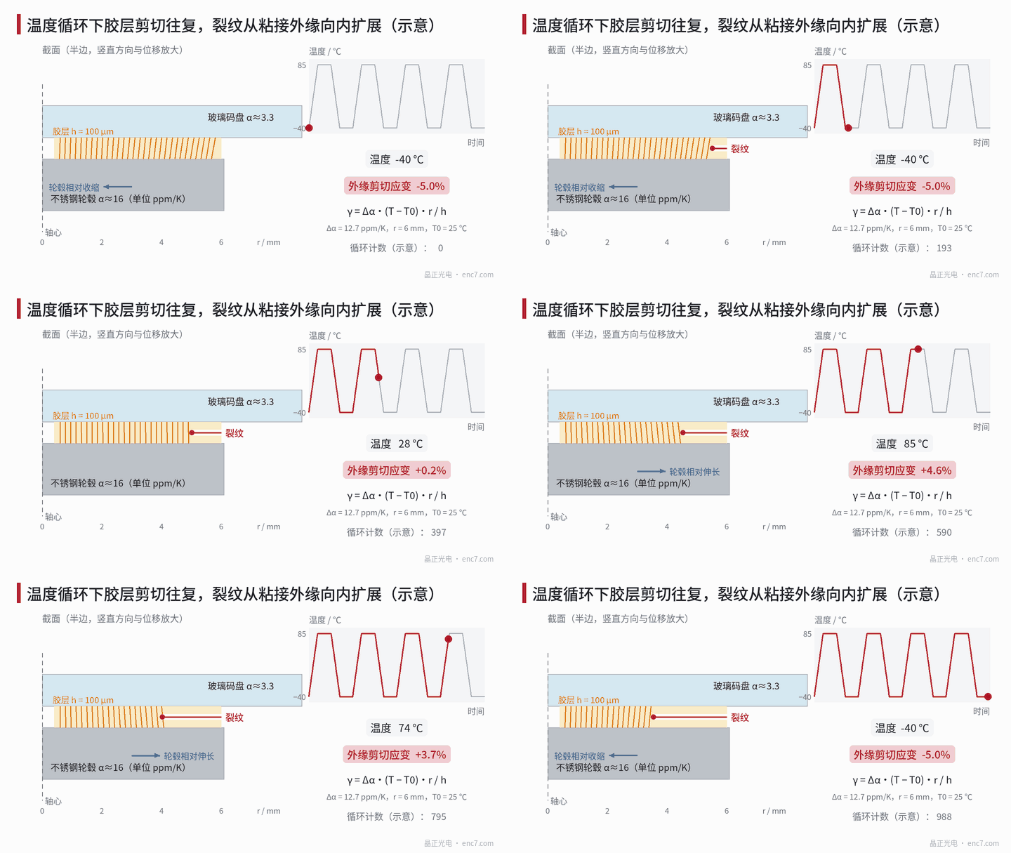
An encoder disc bonded to a hub leaves the factory with acceptable eccentricity; after a few hundred high–low temperature cycles the eccentricity has drifted, and in severe cases the disc comes loose. The usual root cause is not “ageing” of the adhesive but fatigue: glass and metal differ several-fold in expansion coefficient, so every rise and fall of temperature shears the bond line once more, and microcracks start at the outer bond edge and grow inward turn by turn.
Thermal-mismatch shear strain
Taking the axis as the centre of symmetry, when temperature changes by ΔT relative to a stress-free temperature T0 the radial displacement difference between hub and disc at radius r is
u(r) = Δα·ΔT·r
With bond-line thickness h the shear strain is
γ(r) = Δα·ΔT·r / h
where Δα is the difference of the linear expansion coefficients of the two substrates. Strain is zero on the axis and maximum at the outer bond radius—that is why cracks start at the outer edge.
The formula assumes that both substrates are rigid relative to the adhesive, so the whole mismatch displacement is taken up by the bond line. For soft adhesives such as silicone rubber or polyurethane that is quite accurate; for a hard epoxy the substrates themselves deform, the formula gives an upper bound, and the disc and hub share part of the stress.
T0 also matters: for a room-temperature-cure adhesive T0 is about room temperature; for a heat-cure adhesive T0 is near the cure temperature, so at room temperature the bond line already carries a pre-strain and the strain under a −40/+85 ℃ cycle is no longer symmetric.
Worked example: how large is the strain?
A borosilicate-glass disc (α ≈ 3.3×10⁻⁶/K) bonded to a stainless-steel hub (α ≈ 16×10⁻⁶/K) gives Δα = 12.7×10⁻⁶/K. Outer bond radius 6 mm, bond thickness 100 μm, cycle −40/+85 ℃ (ΔT = 125 K):
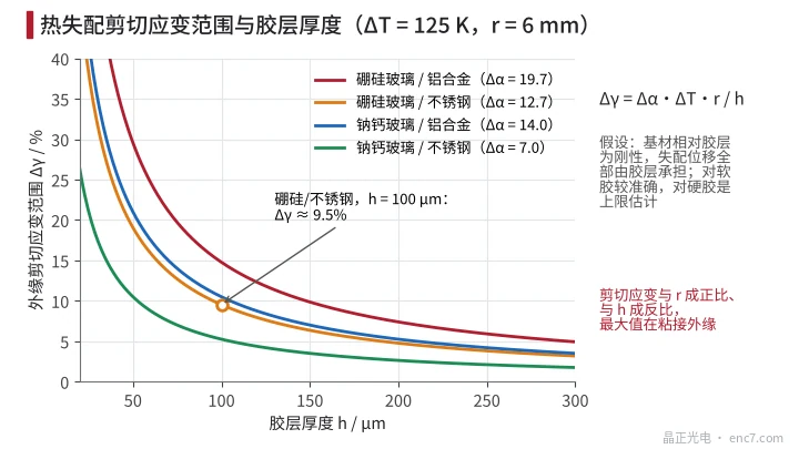
u = 12.7×10⁻⁶ × 125 × 6 mm ≈ 9.5 μm Δγ = 9.5 μm / 100 μm ≈ 9.5%
With an aluminium hub, Δγ ≈ 14.8%; with soda-lime glass on stainless steel, Δγ ≈ 5.3%; halving the bond thickness to 50 μm doubles every value (Figure 2).
What does that magnitude mean? Soft adhesives have a shear modulus of order 1 MPa, so 9.5% strain corresponds to about 0.1 MPa of shear stress—the adhesive can carry it, but only if elongation capacity and fatigue resistance are adequate. A hard epoxy has a shear modulus of order 1 GPa, so the same strain corresponds to about 95 MPa, already beyond the several-tens-of-MPa shear strength of typical structural adhesives; the bond line cannot “swallow” the whole mismatch, and the result is either cracking of the adhesive or stress transferred into the glass—the latter being a common cause of cracking at the bore edge of glass encoder discs.
Coffin–Manson relation and conversion
The empirical low-cycle fatigue life versus cyclic strain range is
N_f = C·Δγ^(−n)
where N_f is the number of cycles to failure and C and n are constants that depend on material, temperature and dwell time. The classical form uses plastic (inelastic) strain; adhesives are usually fitted to measured total strain or inelastic strain.
Within a given structure Δγ is proportional to ΔT, so the acceleration factor between test and use is
AF = (ΔT_s / ΔT_u)^n
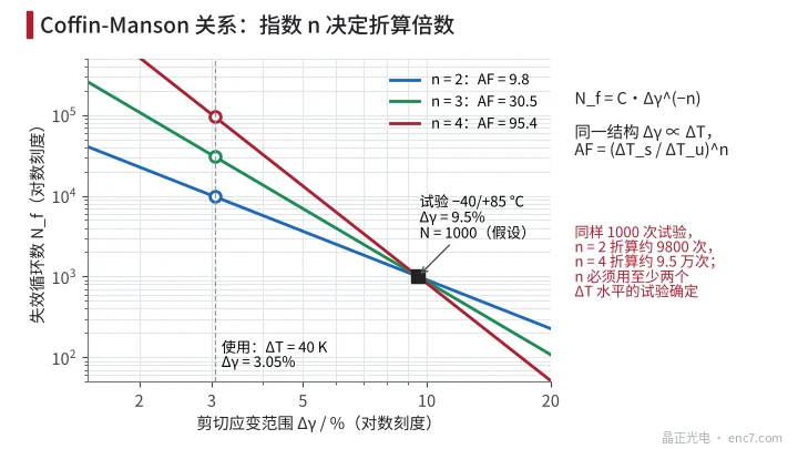
Example: test −40/+85 ℃ (125 K), use a 40 K swing from equipment start–stop. For n = 2, 3, 4, AF = 9.8, 30.5, 95.4. If the median test life is 1000 cycles (assumed), conversion to use conditions gives about 9800, 3.1×10⁴ and 9.5×10⁴ cycles; at 2 start–stop cycles per day that is about 13, 42 and 131 years (Figure 3). A difference of 2 in n changes the conclusion by nearly a factor of 10, so n must be obtained from tests at at least two ΔT levels and must not be borrowed from solder-joint values.
In addition, the longer the high-temperature dwell, the more completely a viscoelastic adhesive creeps and the larger the inelastic strain per cycle; the solder field uses a Norris–Landzberg correction for frequency and peak temperature, and the same class of effects exists in bond lines.
Trade-offs in bond-line design
| Measure | Effect on life (n = 2) | Cost |
|---|---|---|
| Bond thickness 50→100 μm | Δγ halved, life about ×4 | More creep; thickness scatter tends to raise axial runout |
| Outer bond radius 6→5 mm (inner radius 3 mm) | Δγ down to 0.83, life about ×1.44 | Torsional capacity falls to about 52% by r_o³ − r_i³ |
| Hub material with closer expansion coefficient | Δα reduced directly | Material cost and machinability |
| Soft adhesive | Stress greatly reduced | Low stiffness; disc may shift under shock or heat → eccentricity drift |
Bond-thickness consistency matters just as much: glass microspheres of a controlled size mixed into the adhesive, or spacers for limit stops, keep thickness under control; fillets that spill past the outer edge change the edge stress distribution, so the process must specify how they are cleaned.
How to design a temperature-cycling test
- Method: follow IEC 60068-2-14 temperature-change testing; Na is two-chamber rapid transfer, Nb is a specified rate of change. Bond-line fatigue usually uses Nb, with a rate of change close to the real duty.
- Temperature and dwell: highest temperature below the adhesive Tg with margin; dwell long enough for disc, bond line and hub to reach equilibrium and to cover creep relaxation of the adhesive.
- Stress levels: at least two ΔT levels, at least 8~10 pieces each; fit failure cycles with Weibull or lognormal to obtain n.
- Failure criterion: define by function. A 1 μm eccentricity change at r = 20 mm is about 10″, so eccentricity or axial-runout change can be the primary criterion, with torque retention and debond area seen through the glass as secondary.
- Interim inspection: remove and measure about every 100 cycles, recording the cycle count at which cracking or debonding starts.
- Prevent condensation: on the low-to-high transition the surface may dew; moisture uptake adds another degradation mechanism, so control chamber humidity or assess it separately.
Engineering points
- First estimate outer-edge strain with Δγ = Δα·ΔT·r/h; if a soft adhesive exceeds its tolerable fatigue strain, or if a hard adhesive’s calculated shear stress exceeds its strength, the structure must be changed.
- Keep the bond zone as close to the axis as possible: strain is proportional to r, but torsional capacity scales with r³—both must be checked together.
- Bond thickness needs a lower limit and must be controllable; use microspheres or spacers for consistency so that locally thin spots do not become crack starters.
- For heat-cure adhesives take the cure temperature as the stress-free temperature and assess the pre-strain at room temperature and at the cold end.
- Before converting life, obtain n from two or more ΔT levels; with only one level you can run a comparison test, not a life extrapolation.
- Use eccentricity and axial-runout change as the primary failure criteria—they map directly onto the encoder’s angular error.
Summary
Under temperature cycling the shear-strain range in the bond line is about Δα·ΔT·r/h; for glass on metal it easily reaches several to more than ten percent. The Coffin–Manson relation links strain to life, but the exponent n dominates the conversion and must be determined by test. Bond-line design balances thickness, bond radius and adhesive stiffness, and eccentricity drift is the final acceptance criterion.
Translated from the ENC7 Chinese technical library (article 0194). Read the Chinese original. Need a disc built to your drawing? Request a quote or see our custom encoder discs.
© Langfang Jingzheng Optoelectronic Technology Co., Ltd. All rights reserved. This article was created with AI assistance.