Industry applications in depth
All-electric injection moulding: screw position and V–P switchover
In an all-electric injection moulding machine a servo motor drives the screw through a ball screw. This article calculates a resolution of 19 nm for a 20 mm lead and 2²⁰ counts, shows that the shot-size error at the velocity-to-pressure switchover, ΔV = A·v·T_d, is set mainly by sampling delay, gives allowable values for delay and jitter, and compares these with elastic and thermal errors outside the encoder.
On an all-electric injection moulding machine the screw is driven by a servo motor through a ball screw, and injection speeds can reach several hundred mm/s. The position at which control switches from velocity to pressure at the end of filling determines the volume of melt that enters the cavity in each shot, so shot-to-shot repeatability is, to a considerable extent, simply the position repeatability of the switchover point. What does that mean for the encoder on the motor? The conclusion is somewhat counter-intuitive: resolution is under almost no pressure; what is really tight is time.
Position resolution: far more than is needed
Assume the motor is coupled directly to the ball screw, the lead is 20 mm, and the encoder produces 2²⁰ = 1 048 576 counts per revolution. Then
displacement per count = 20 mm ÷ 1 048 576 = 19.07 nm
The cross-sectional area of a Ø40 mm screw is A = π·20² = 1256.6 mm², and a displacement Δx corresponds to a volume ΔV = A·Δx. A switchover-position difference of 0.01 mm is already 12.6 mm³, equivalent to 524 counts, whereas 1 count corresponds to only 0.024 mm³. If the moulded-part volume is 5 cm³, 12.6 mm³ is about 0.25%; this is an upper-bound estimate that charges the entire deviation to the filled volume, and the packing stage will compensate part of it.
To hold position quantization down to 1/10 of 0.01 mm (1 μm), only 20 mm ÷ 1 μm = 20 000 counts per revolution are needed, so 15 bits are enough. An encoder accuracy of ±100″ refers to the screw as 100/1 296 000 × 20 mm = 1.5 μm, which is likewise not the leading term.
Sampling delay: position error equals velocity times delay
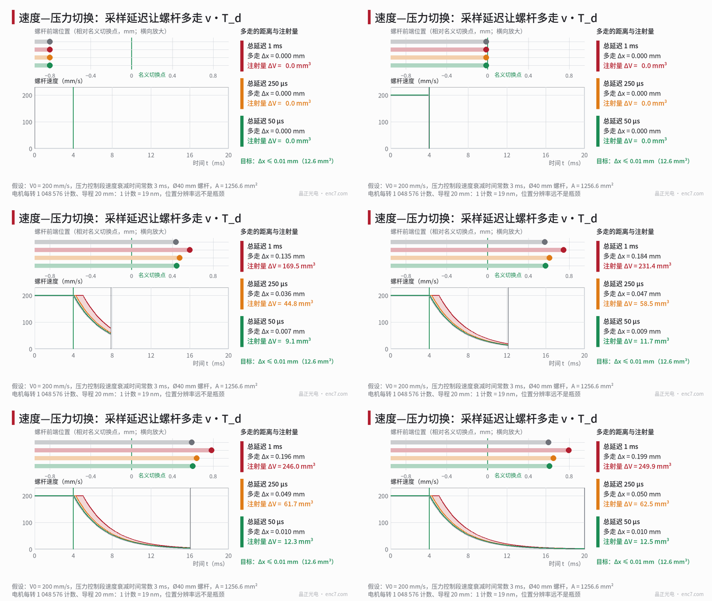
The screw advances at velocity v. From the instant the switchover position is reached to the actual switch, the controller incurs a total delay T_d, so the switch is late by
Δx = v·T_d, ΔV = A·v·T_d
T_d is the series combination of three segments: transfer through the encoder interface (a few microseconds when a serial frame is some tens of bits at a 10 MHz clock), the sample period of the drive position loop (commonly 62.5–125 μs), and the controller scan period (millisecond scale). Results at A = 1256.6 mm² are as follows:
| Total delay T_d | Δx (100 mm/s) | Δx (200 mm/s) | Δx (300 mm/s) | ΔV (200 mm/s) |
|---|---|---|---|---|
| 10 μs | 0.001 mm | 0.002 mm | 0.003 mm | 2.5 mm³ |
| 50 μs | 0.005 mm | 0.010 mm | 0.015 mm | 12.6 mm³ |
| 125 μs | 0.0125 mm | 0.025 mm | 0.0375 mm | 31.4 mm³ |
| 250 μs | 0.025 mm | 0.050 mm | 0.075 mm | 62.8 mm³ |
| 1 ms | 0.100 mm | 0.200 mm | 0.300 mm | 251 mm³ |
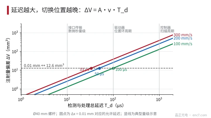
It follows that a controller scan period on the 1 ms scale cannot be used at all to decide the switchover; the position comparison must be placed in the drive or in hardware.
What remains after compensation
The mean value of the delay can be compensated: trigger early according to the estimated velocity, and switch at x_s − v·T_d. What remains after compensation is delay jitter, which is generally taken as 1/3 of the allowable Δx:
ΔT_j ≤ 0.0033 mm ÷ 200 mm/s = 17 μs
If the drive position loop decides only once every 62.5 μs, and the decision instant is uniformly distributed relative to the arrival instant, the peak-to-peak error at 200 mm/s is 12.5 μm, already more than 10 μm; at 125 μs it is 25 μm. So the switchover should be performed by a hardware position compare: the encoder signal enters a counter and a trigger is issued directly when it equals the compare register, leaving only a few microseconds of delay.
Velocity estimation also depends on quantization. When the velocity loop differences over 62.5 μs, the velocity quantization of a 17-bit encoder is 0.153 μm ÷ 62.5 μs = 2.4 mm/s (1.2% of 200 mm/s), and that of a 20-bit encoder is 0.3 mm/s (0.15%). The significance of 2²⁰ is velocity smoothness, not position.
Errors outside the encoder
What the encoder sees is motor angle; the true position of the screw also includes the drive train:
- Axial elasticity: assume a melt pressure of 80 MPa at switchover; the force on the screw is 80 MPa × 1256.6 mm² = 100.5 kN; if the combined axial stiffness of the ball screw, bearings and frame is 1.5 kN/μm, the deflection is 67 μm, and a pressure fluctuation of ±10% is already ±6.7 μm.
- Thermal expansion: a steel ball screw is about 11–12×10⁻⁶/K; over a 100 mm stroke and a 10 K temperature rise the expansion is about 11.5 μm.
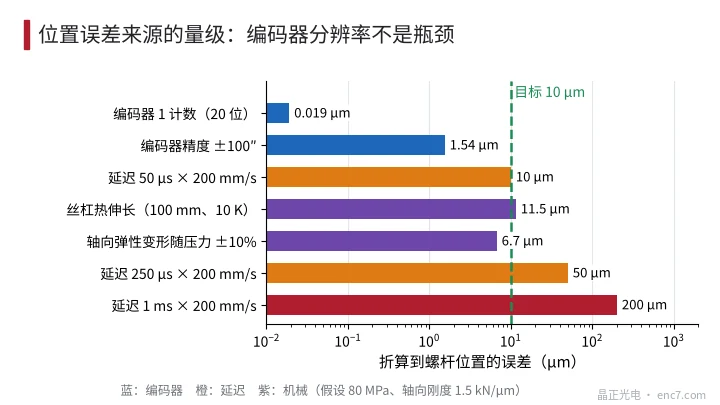
Neither of these terms depends on encoder resolution; they can only be handled by pressure compensation, periodic homing, or by measuring position directly on the screw.
Engineering takeaways
- Position quantization need only be smaller than 1/10 of 0.01 mm; 15 bits are enough, and the value of 20 bits lies in the smoothness of the velocity loop.
- Size the delay from T_d ≤ allowable Δx ÷ v: 0.01 mm at 200 mm/s corresponds to 50 μs; place the switchover decision in the drive or in a hardware position compare.
- After compensating the mean delay, control jitter to 1/3 of the allowable value, about 17 μs at 200 mm/s.
- The transfer time and refresh period of the encoder interface must be included in T_d, and the sampling instant of a serial protocol should be synchronised with the control period.
- Treat elasticity and thermal expansion by pressure compensation or by homing; the example at 80 MPa and 1.5 kN/μm already has 67 μm of deflection.
- The motor end is hot and sees shock, so the disc substrate and the readhead must be selected for temperature and vibration.
Closing
The position requirement on the injection screw is of the order of 0.01 mm, yet a 20-bit encoder can already resolve 19 nm. The deviation of the switchover point is set by v·T_d; at 200 mm/s a delay of 50 μs uses up the entire allowance, and a 1 ms scan period would inject about 251 mm³ extra. To achieve shot-to-shot repeatability, the decision delay should be shortened and made stable, and the drive-train elasticity and thermal expansion that the encoder cannot see should be faced squarely.
Translated from the ENC7 Chinese technical library (article 0764). Read the Chinese original. Need a disc built to your drawing? Request a quote or see our custom encoder discs.
© Langfang Jingzheng Optoelectronic Technology Co., Ltd. All rights reserved. This article was created with AI assistance.