Testing, reliability & quality
Angle Traceability: Linking Encoder Accuracy to National Standards
An encoder is specified at ±5″ – what makes that number stand up? This article traces the chain from the national angle standard through reference standards and working standards to the product, explains the circle-closure principle and the polygon cross-calibration method, calculates how uncertainty accumulates level by level, and distinguishes calibration from verification.
An encoder data sheet says “accuracy ±5″”. That number was obtained by comparison with a reference encoder on a test bench; and who calibrated the reference encoder’s error? Follow the chain further up and it must end at the national angle standard. If any link in that chain lacks a record or an uncertainty, ±5″ is just “a measured number”, not a quantity value that can be compared with anyone else’s.
Three requirements of traceability
Metrological traceability means that a measurement result can be related to a reference through a documented, unbroken chain of calibrations, each of which contributes to the final uncertainty (term defined in JJF 1001, China’s national metrology vocabulary). In practice this comes down to three things:
- An unbroken chain: every standard at every level has a valid calibration certificate and is used within its calibration interval;
- An uncertainty: every certificate states the measured value and its expanded uncertainty, not just “pass”;
- Records: method, environment, personnel and equipment status are traceable; laboratory competence is usually assessed to ISO/IEC 17025.
Traceability does not mean “very accurate”. A test bench with a complete traceability chain but an uncertainty of 2″ is barely adequate for verifying a ±5″ product.
What makes angle special: the circle is its own standard
A length standard needs an external reference; angle is different. The radian is the ratio of arc length to radius, and the full circle is exactly 2π, so if the circle is divided into N parts, the sum of the division errors must be zero:
Σδ_i = 0
This “circle closure” principle allows high-level angle standards to be self-calibrated without relying on a higher-level external artefact. A typical method is cross-calibration of an optical polygon against a rotary table, see Figure 2.
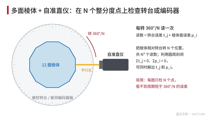
Let t_j be the error of the rotary table at the j-th whole-division position and p_i the angular deviation of the i-th polygon face. The polygon is set in turn to k = 0…N−1 positions relative to the table, and a full revolution is measured in each position; the autocollimator reading is:
r_jk = t_j + p_(j−k) + c_k
where c_k is the autocollimator zero after each set-up (arbitrary). Using Σt_j = 0 and Σp_i = 0: averaging over j for fixed k gives c_k; after subtracting it, averaging over k gives t_j; the polygon errors p_i then follow.
Worked example: how accurate is cross-calibration?
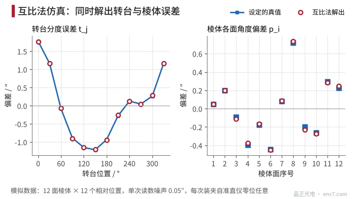
Simulation with a 12-face polygon (simulated data): table errors set between −1.2″ and +1.8″, polygon face deviations within ±0.8″, single-reading noise 0.05″, random zero at each set-up. The table and polygon errors solved from the 144 readings deviate from the set values by at most about 0.03″, see Figure 3. In theory the single-point error is about σ·√(N−1)/N, which for σ = 0.05″ and N = 12 is about 0.014″, consistent with the statistics of 2000 Monte Carlo runs.
The same closure principle applies to multiple readheads: averaging M readheads evenly spaced around a circular grating cancels all harmonic error components except integer multiples of M. Reference rotary tables often use this to raise their own accuracy.
How uncertainty accumulates level by level
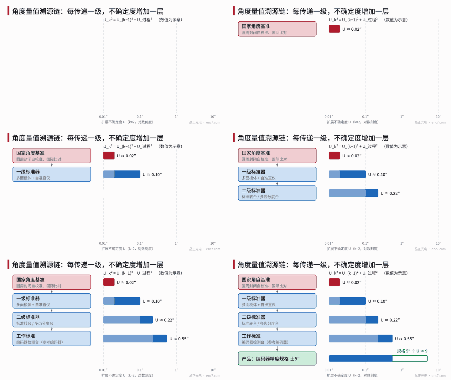
The uncertainty at the next level consists of two parts: the uncertainty of the standard at the level above, and the uncertainty introduced by this level’s comparison process (set-up, alignment, temperature, reading resolution and so on). If the two are independent they combine as a root sum of squares:
U_k² = U_(k−1)² + U_process,k²
Illustrative values from Figure 1: national standard 0.02″, via optical polygon + autocollimator 0.10″, via reference rotary table 0.22″, at the encoder test bench 0.55″. The ratio of the product specification ±5″ to 0.55″ is about 9, so the measurement capability is sufficient.
These numbers show an often overlooked fact: the further downstream, the more the process term of the level itself dominates. Of the test bench’s 0.55″, the upstream chain contributes only 0.22″; coupling transmission error, mounting eccentricity of the encoder under test and the interpolation error of the reference encoder are the big items. Improving the test bench is usually more effective than chasing a higher-grade upstream certificate.
Note also the limits of sampling: a 24-face polygon checks only one point every 15°, so error components with periods shorter than 30° are aliased or missed, and interpolation error (whose period is one signal period) is completely invisible. Short-period errors must be verified with a continuously comparing reference encoder.
Calibration and verification are not the same thing
| Item | Verification | Calibration |
|---|---|---|
| Nature | Legal metrology; instruments on the mandatory verification list must be verified | A technical activity, usually commissioned voluntarily |
| Basis | Metrological verification regulation (JJG) | Calibration specification (JJF) or agreed technical document |
| Conclusion | Pass or fail | Measured value and uncertainty, usually no conformity decision |
| Interval | Set by the regulation | Set by the user according to use |
In-house standards such as encoder test benches and optical polygons are mostly calibrated. Once the calibration certificate is in hand, the user must judge for themselves whether the errors and uncertainty stated in it meet their own testing requirements. Between calibrations, intermediate checks with a check standard should be carried out to detect drift of the standard in time.
Engineering points
- The traceability evidence of a test bench must lead all the way to the higher-level certificates: certificate numbers and validity of the reference encoder, polygon and autocollimator should be recorded in every test report.
- State the test uncertainty together with the encoder accuracy; when specification ÷ U falls below 3–4, the decision should take a guard band into account.
- In a test bench uncertainty budget, mounting eccentricity, coupling and temperature are usually larger than the upstream certificate; improve these process terms first.
- The polygon method suits only long-period errors; interpolation error and short-period graduation errors need continuous comparison or a high-speed time-interval method.
- When a calibration certificate gives no “pass” statement, the user must compare the errors with the permissible values themselves – do not take “calibrated” to mean “conforming”.
- Use a stable encoder or polygon as a check standard, measure it monthly or per batch and plot a control chart as the record of intermediate checks.
Summary
Angle traceability starts from circle closure; self-calibration lets high-level standards do without an external reference. Along the chain from national standard to reference standard, working standard and product, uncertainty grows level by level as a root sum of squares, and the downstream process terms often dominate. For encoder accuracy to be properly linked to the standard, the chain must be complete, every level must state its uncertainty, and intermediate checks must be kept up during use.
Translated from the ENC7 Chinese technical library (article 0192). Read the Chinese original. Need a disc built to your drawing? Request a quote or see our custom encoder discs.
© Langfang Jingzheng Optoelectronic Technology Co., Ltd. All rights reserved. This article was created with AI assistance.