Glass & substrate science
Anisotropic Expansion of Crystal Substrates: How Unequal In-Plane Expansion Produces 2nd-Order Angular Error

Single-crystal substrates have different linear expansion coefficients along different crystal axes. When in-plane expansion on a wafer face is unequal, radial scribe lines deflect at a 2× angle. This article derives the error amplitude Δα·sin²ν·ΔT/2, computes about 5″ for sapphire A-plane and about 31″ for quartz X/Y cuts (ΔT = 50 K, example parameters), and gives remedies in orientation, readhead layout and temperature compensation.
Amorphous glass expands isotropically: a temperature rise only enlarges the disc slightly and leaves the angular positions of radial lines unchanged. With a single-crystal substrate (sapphire, crystalline quartz) the picture changes: the linear expansion coefficient varies with direction, so a wafer whose two in-plane axes expand unequally turns a circle into an ellipse on heating and the radials deflect with it. The error appears twice per revolution, is independent of read radius, and diametrically opposed dual readheads cannot cancel it. This article takes the effect from the thermal-expansion tensor down to arcseconds and answers two engineering questions: which cuts are safe, and how to suppress the rest.
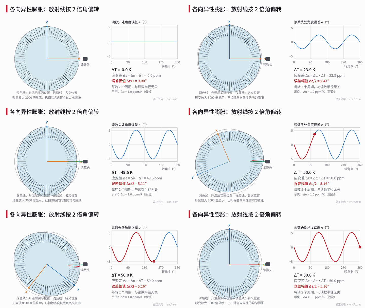
Model: from the expansion tensor to 2nd-order angular error
For trigonal, hexagonal and tetragonal systems (sapphire and α-quartz among them) the linear expansion coefficient has only two independent values: α∥ along the optic axis (c-axis) and α⊥ perpendicular to it. For an arbitrary direction at angle χ to the c-axis:
α(χ) = α⊥ + (α∥ − α⊥)·cos²χ = α⊥ + Δα·cos²χ
where Δα = α∥ − α⊥. When the wafer normal makes an angle ν with the c-axis, the face has two principal axes: one along the in-plane projection of the c-axis (at 90° − ν to the c-axis), with expansion α⊥ + Δα·sin²ν; the other perpendicular to the c-axis, with expansion simply α⊥. The in-plane difference is
Δα_eff = Δα·sin²ν
It is 0 for the C-plane (ν = 0), Δα for the A-plane (ν = 90°), and 0.713·Δα for the R-plane (normal about 57.6° from the c-axis). Cubic silicon has no such problem: its thermal-expansion tensor is isotropic (elastic anisotropy is a separate matter).
Suppose the lines are written as ideal radials at T₀. After a rise ΔT the principal strains are ε_x = α_x·ΔT and ε_y = α_y·ΔT. A point (r·cosφ, r·sinφ) at angular position φ in crystal axes moves to (r(1+ε_x)cosφ, r(1+ε_y)sinφ), and the angular offset satisfies
tan(φ + δ) = (1+ε_y)/(1+ε_x)·tanφ, δ ≈ (ε_y − ε_x)/2 · sin2φ
Error amplitude
A₂ = Δα_eff·ΔT / 2
where φ is measured from the x-axis. Three properties follow: independent of radius r; the isotropic part of uniform expansion drops out entirely; deflection is largest at φ = 45°. With a fixed readhead and one disc revolution, φ sweeps 360° and the error shows two periods (Figure 1, right). The same form appears on stretched plastic-film discs (see another article in this library); for crystals the anisotropy comes from the lattice and barely changes from lot to lot.
Worked example: 50 K temperature difference
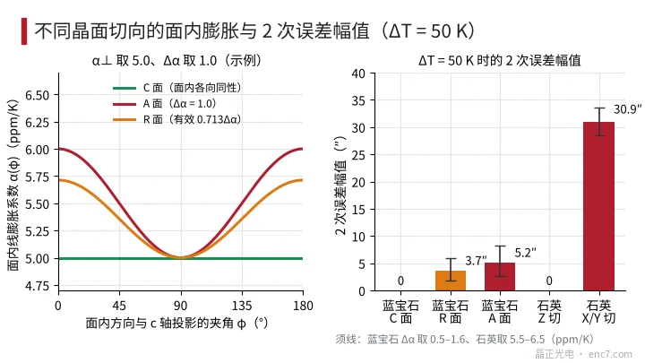
Take ΔT = 50 K (relative to the write temperature). Literature values of sapphire Δα are of order 1 ppm/K, but the exact number, the sign and even the temperature dependence disagree among sources; the table below uses three example tiers 0.5, 1.0 and 1.6 ppm/K. For α-quartz, α∥ is about 7.1–7.5 and α⊥ about 13.2–13.7 ppm/K, so Δα is about 6 ppm/K (the sign is unrelated to sapphire and only shifts the phase).
| Substrate and cut | Δα_eff (ppm/K) | Δε = Δα_eff·ΔT | 2nd-order amplitude |
|---|---|---|---|
| Sapphire C-plane | 0 | 0 | 0 |
| Sapphire R-plane (Δα = 1.0) | 0.71 | 36 ppm | about 3.7″ |
| Sapphire A-plane (Δα = 0.5 / 1.0 / 1.6) | 0.5 / 1.0 / 1.6 | 25 / 50 / 80 ppm | about 2.6″ / 5.2″ / 8.3″ |
| Quartz Z-cut | 0 | 0 | 0 |
| Quartz X or Y cut (Δα ≈ 6) | 6 | 300 ppm | about 31″ |
For the A-plane with Δα = 1.0 ppm/K: Δε = 1.0×10⁻⁶ × 50 = 50 ppm, A₂ = 25×10⁻⁶ rad × 206265 ≈ 5.2″. Direct numerical evaluation of the exact arctan gives 5.157″; the small-angle approximation is off by less than three parts in ten thousand. On a 2048-line disc one signal period is about 632.8″, so 5.2″ is 0.8% of a period; the 31″ of quartz X/Y cut is nearly 5% of a period and cannot be ignored where high interpolation is needed. Conversely, to keep the 2nd-order error within 1″ the allowed temperature excursion is
ΔT_max = 2·e_max / Δα_eff
With e_max = 1″ = 4.85 μrad, A-plane sapphire (Δα = 1.0) allows about 9.7 K, R-plane about 13.6 K, and quartz X/Y cut only about 1.6 K.
Remedies: orientation, readheads and temperature compensation
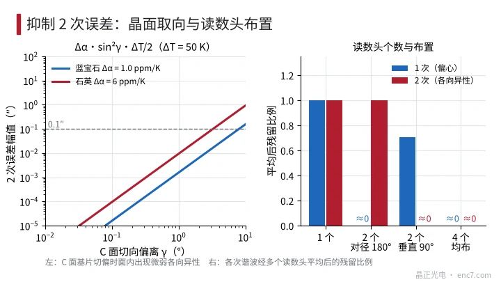
1. Prefer the C-plane (sapphire) or Z-cut (quartz). With the optic axis normal to the disc the face is isotropic and the 2nd-order term is zero. When the cut is off by γ, the in-plane difference Δα·sin²γ falls as the square: at γ = 1° it is only 3×10⁻⁴ of Δα; for sapphire Δα = 1.0 ppm/K and ΔT = 50 K, γ = 5° still gives only about 0.04″, and Z-cut quartz at γ = 5° about 0.24″ (Figure 3, left). So C-plane cut tolerance can be relaxed to the degree level; there is no need to pay extra for it.
2. Lay out readheads by harmonic. Averaging N readhead signals leaves a residual fraction |Σe^(ikφ_j)|/N of the k-th harmonic. Diametrically opposed heads (180°) cancel the 1st (eccentricity) but fully retain the 2nd; two heads 90° apart cancel the 2nd exactly while leaving 0.707 of the 1st; four heads equally spaced cancel both (Figure 3, right). If an A- or R-plane must be used, either adopt a 90° or four-head layout, or accept the table amplitudes over the temperature range.
3. Temperature compensation. A₂ = Δα_eff·(T − T₀)/2 is locked to the crystal axes: phase is set by the axis orientation relative to the readhead, amplitude is proportional to the temperature difference from write. Record the axis direction at factory calibration, measure temperature in service, and those two parameters yield the correction. Note that on cooling the amplitude reverses sign.
4. Other differences. A- and R-plane wafers are birefringent (sapphire Δn about 0.008; 1 mm thickness near 850 nm gives about 9 waves of retardance), so polarisation-sensitive readout must be checked; C-plane light travels along the c-axis and produces no birefringence at normal incidence.
Engineering notes
- In-plane anisotropy error A₂ = Δα·sin²ν·ΔT/2, independent of read radius; invert ΔT_max = 2·e_max/Δα_eff for the allowed temperature excursion.
- Prefer sapphire C-plane; within 5° of cut error Δα_eff shrinks by more than two orders of magnitude. Use A- or R-plane only with a clear reason.
- Prefer quartz Z-cut; X/Y cuts have Δα about 6 ppm/K and about 31″ error at 50 K — unsuitable for high interpolation.
- Neither a single readhead nor diametric dual heads suppress the 2nd harmonic; use 90° or four-head equal spacing when needed.
- Sapphire Δα magnitude and sign vary by reference; before selecting, ask the supplier for measured expansion data, or calibrate the 2nd harmonic yourself with a thermal cycle.
- In thermal-cycle validation, Fourier-decompose the full-circle error and watch the 2nd component versus temperature separately from the 1st (eccentricity).
Summary
Thermal expansion of a single-crystal substrate is described by a second-rank tensor. Whenever the two in-plane principal expansion coefficients differ, a temperature rise produces a twice-per-revolution angular error independent of radius, with amplitude Δα_eff·ΔT/2. Sapphire C-plane and quartz Z-cut are isotropic in-plane and are the appropriate choices; A-plane, R-plane or quartz X/Y cuts must be managed by readhead layout, temperature control and compensation.
Translated from the ENC7 Chinese technical library (article 0571). Read the Chinese original. Need a disc built to your drawing? Request a quote or see our custom encoder discs.
© Langfang Jingzheng Optoelectronic Technology Co., Ltd. All rights reserved. This article was created with AI assistance.