Industry applications in depth
Choosing input and output discs for harmonic-drive TE test stands
Transmission error TE = θ_out − θ_in/i has to be measured with an encoder at each of the input and the output. This article derives the weight with which errors at the two ends convert into TE, shows that input-side resolution and accuracy are diluted by i while output-side accuracy almost decides everything, and, with a worked example at i = 100, gives the requirements on line count, interpolation, eccentricity and synchronous sampling.
The transmission error (TE) of a harmonic drive typically ranges from a few tens of arcseconds to one or two arcminutes. A test stand mounts one encoder on the input shaft and one on the output shaft, and TE is simply the difference of the two angles after conversion. The two encoders look symmetrical, yet their contributions to TE are completely asymmetrical: the input shaft turns fast, and every error on it is reduced by the reduction ratio i; every error on the output shaft enters the result as it stands. Selection has to start from this asymmetry.
Measurement equation and uncertainty
TE = θ_out − θ_in/i
where i is the reduction ratio (an exact integer, fixed by the tooth counts) and θ_in must be accumulated continuously, not taken modulo one revolution. The error sources combine as
u_c² = u_out² + (u_in/i)² + (ω_out·Δt)²
ω_out is the output angular velocity and Δt is the difference between the two sampling instants. Input-side errors are divided by i; a synchronisation error between the two channels, whether the input is sampled first or the output is sampled first, converts into TE as ω_out·Δt.
The expanded uncertainty of the test stand itself should be less than 1/5 to 1/10 of the specification of the measurand. Assuming a peak-to-peak TE specification of ≤ 60″, U should be no greater than 6–12″.
Input side: diluted by i
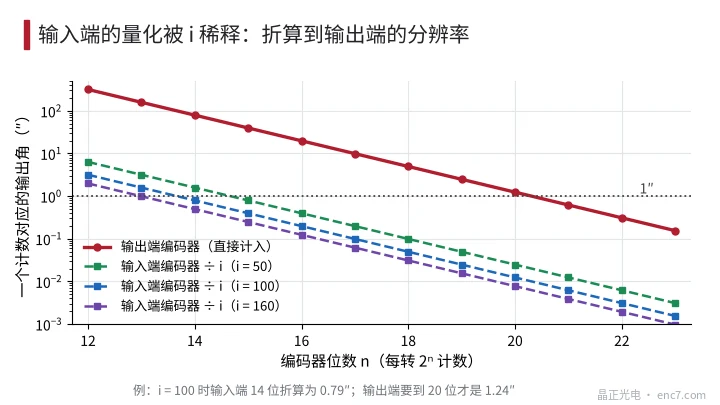
One count q_in of the input encoder, referred to the output, is only q_in/i. To keep q_in/i ≤ 1″ one needs q_in ≤ i arcseconds: for i = 50, 100 and 160 this means 15, 14 and 13 bits (corresponding to 39.5″, 79.1″ and 158.2″). A 17-bit unit, common on the motor side (9.9″), refers to only 0.099″, which is more than enough.
Accuracy is diluted in the same way. In the example the input encoder accuracy is ±40″, or ±0.4″ after referral. With 3 μm of eccentricity at r = 12 mm the first-order error is 51.6″, or 0.52″ after referral. It falls at order i per output revolution, the same order as the order-1 component of the wave generator, and cannot be separated in the spectrum, but its amplitude is small.
Output side: accuracy almost decides everything
Errors of the output encoder enter the result as they stand. Three requirements follow.
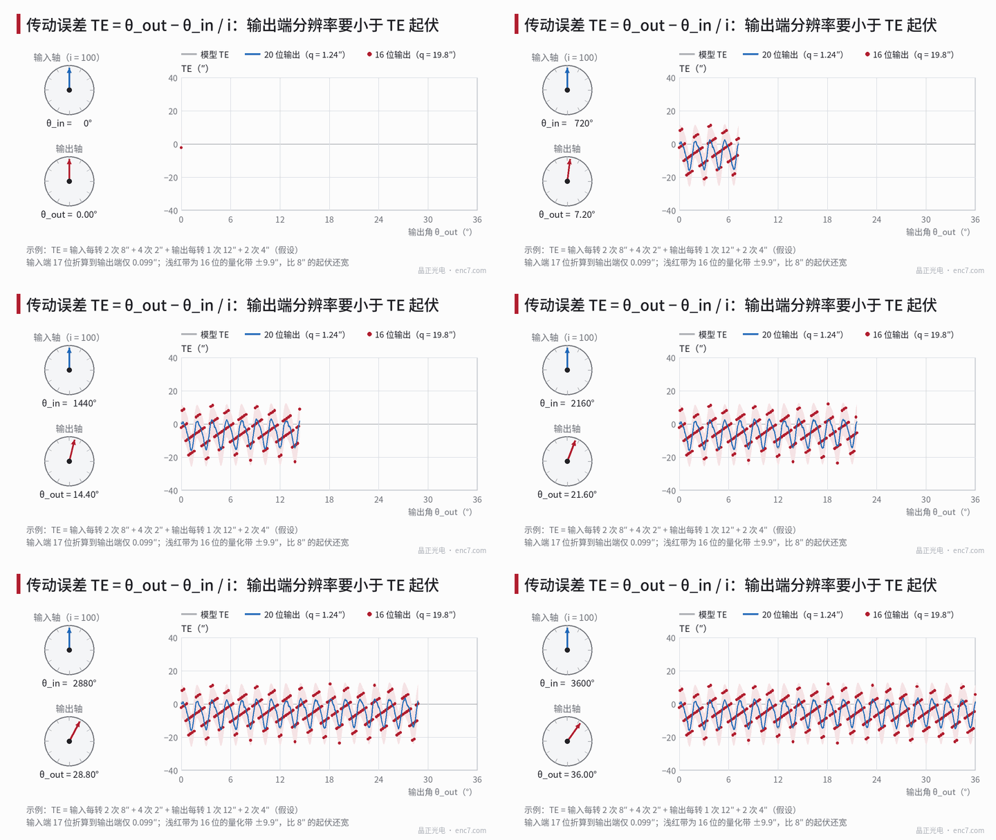
Accuracy: when the other terms can be neglected, U = 2a/√3 ≈ 1.15a (a is the half-width of the accuracy specification), so a must be slightly smaller than 0.87·U. Quantization: q_out must be less than 1/5 of the amplitude of the TE component that needs to be resolved. In Figure 1, 16 bits (19.8″) cannot measure an 8″ order-2 component; 20 bits (1.24″) can make it visible. Low-order error: the encoder’s own eccentricity error occurs 1 time per output revolution, at the same order as the order-1 component of the reducer output, and adds directly as a spurious TE. On a Ø100 mm encoder disc at r = 45 mm, 2 μm of eccentricity is already 9.2″, so the output side should use diametrically opposite dual readheads, or be calibrated first against a reference standard. The encoder disc should be mounted directly on the output flange, not through a coupling; the angular transmission error of a coupling varies with misalignment.
The line count should also avoid the orders of TE. The main TE components lie at orders 2i and 4i in the output angular domain (orders 200 and 400 when i = 100). With a 4096-line output encoder, interpolation error appears at order 4096 and its multiples, which are not integer multiples of 200; if 2000 lines are used, interpolation error falls at integer multiples of 2i and cannot be distinguished from the higher harmonics of TE.
Synchronous sampling
The 2i-order component of TE has a period of only about 1.8° in the output domain. Sampling should be triggered at equal intervals of input angle, with 32 points per input revolution (3200 points per output revolution), giving 16 points per period of the 2i order and 8 points per period of the 4i order, and at least 2 output revolutions should be acquired to check repeatability.
Both channels must be latched on the same trigger edge. At an output speed of 2 r/min (12°/s), ω_out·Δt is 0.43″ for Δt = 10 μs, 4.3″ for 100 μs, and 43″ for 1 ms. A fixed delay difference of a serial interface can be subtracted after calibration; the jitter part has to be controlled by hardware triggering.
Worked example: i = 100, TE specification 60″
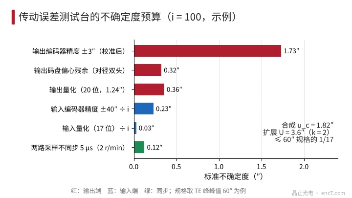
Assumptions: input 17 bits (2048 lines × interpolation factor 64), accuracy ±40″; output a Ø100 mm encoder disc, 4096 lines × interpolation factor 256 (20 bits), diametrically opposite dual heads, accuracy after calibration ±3″, residual eccentricity taken as 5%; output speed 2 r/min, synchronisation error 5 μs.
| Error source | Amplitude | Standard uncertainty |
|---|---|---|
| Output encoder accuracy | ±3″ | 1.73″ |
| Residual eccentricity of the output disc | 0.46″ | 0.32″ |
| Output quantization | 1.24″ | 0.36″ |
| Input encoder accuracy ÷ i | ±0.4″ | 0.23″ |
| Input quantization ÷ i | 0.099″ | 0.03″ |
| Synchronisation, 5 μs | 0.22″ | 0.12″ |
The combined uncertainty is u_c = 1.82″, and U (k = 2) = 3.6″, about 1/17 of the specification.
Effect of changes: if the input side is reduced to 12 bits (3.2″ after referral), U rises only to 4.1″ and still meets 1/10; if the output side is used without diametrically opposite heads and the full 9.2″ from 2 μm of eccentricity is included, U rises to about 13.4″, which exceeds 1/5 (12″). If the specification is tightened to 15″, output-side accuracy must reach the ±1″ class, in which case U is about 1.6″ (about 1/9), and 17 bits on the input side is still enough.
Engineering takeaways
- Choose the bit depth on the input side from q_in ≤ i arcseconds; 13–17 bits is enough, and a high-accuracy encoder is not necessary.
- Take the half-width of output-side accuracy to be less than 0.87 times U, keep quantization below 1/5 of the amplitude of the TE component to be resolved, and remove the order-1 eccentricity term with diametrically opposite dual readheads or by calibration.
- Latch both channels on the same hardware trigger edge, size the synchronisation requirement from ω_out·Δt, and subtract any fixed interface delay difference.
- Sample at equal intervals of input angle, with at least 32 points per input revolution, and take an integer number of output revolutions, so that the 2i and 4i orders of TE do not leak.
- Avoid a line count on the output encoder that is an integer multiple of 2i; mount the output encoder disc directly on the output flange, not through a coupling.
- Each time the specification is tightened by half, the investment priority is output-side accuracy, not input-side resolution.
Closing
The two encoders on a TE test stand differ in weight by a factor of i: resolution, accuracy and eccentricity on the input side are all diluted by i, while those on the output side enter as they stand. A conventional mid-range-bit encoder is therefore enough on the input side; the budget should be concentrated on output-side accuracy, dual readheads and direct mounting, with hardware triggering to keep the two channels in synchronism.
Translated from the ENC7 Chinese technical library (article 0762). Read the Chinese original. Need a disc built to your drawing? Request a quote or see our custom encoder discs.
© Langfang Jingzheng Optoelectronic Technology Co., Ltd. All rights reserved. This article was created with AI assistance.