Encoder-disc terminology
Clear-Area Transmittance: Glass, Residual Film and Surface State
The signal ceiling of a transmissive encoder disc is set by clear-area transmittance: the two uncoated surfaces of soda-lime glass already lose about 8% by reflection, and sub-nanometre residual chrome, a thin oxide, developer residue and water marks can take off several more percentage points. This article derives the light-to-dark ratio and modulation depth fixed jointly by transmittance and OD, and gives measurement methods, acceptance criteria and common misuses of measurements in the graduated area.
A batch of discs all passed incoming inspection on OD, yet after installation the signal amplitude was about 5% lower than the previous batch, and it varied from disc to disc. The problem was not that the chrome areas were not black enough, but that the clear areas were not clear enough. In transmissive scanning the alternating signal at the detector is proportional to the difference in transmittance between the clear area and the chrome area; once the chrome OD is above 3, that difference is almost equal to the clear-area transmittance. Clear-area transmittance sets the ceiling of the signal, yet it is often assumed to be perfectly transmitting.
What makes up clear-area transmittance
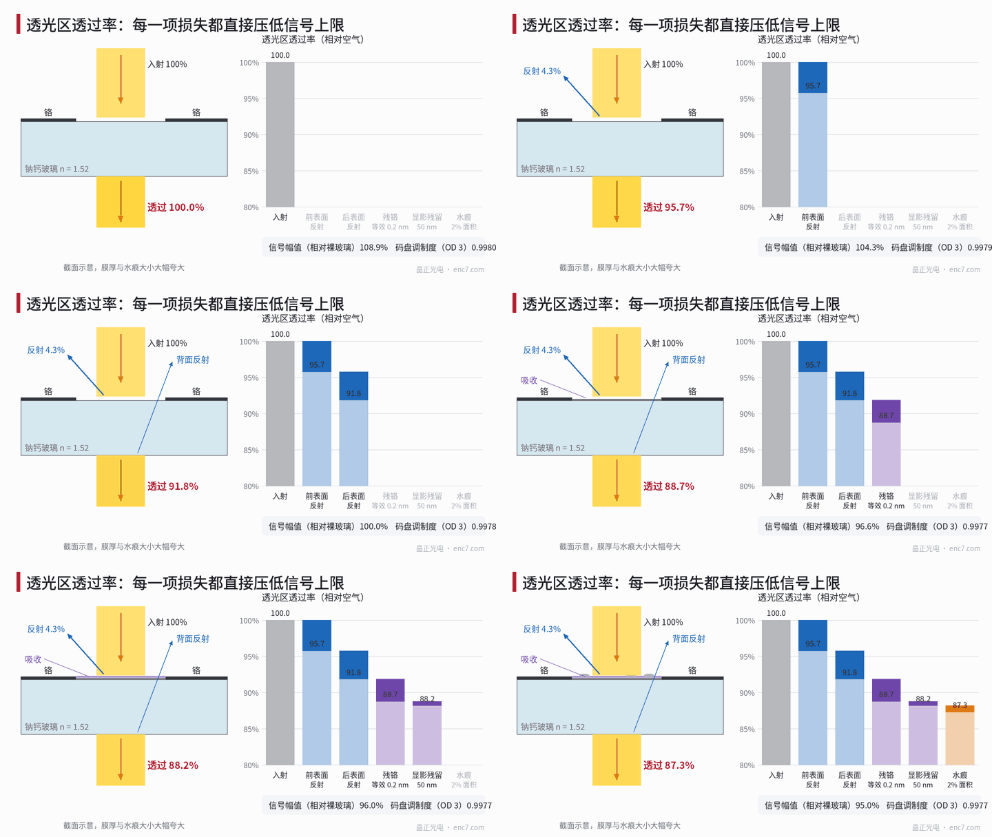
Fresnel reflection at the two glass surfaces. At normal incidence the single-surface reflectance is
R = ((n − 1)/(n + 1))²
For soda-lime glass with n = 1.52, R = 4.26%. Superposing multiple incoherent reflections between the two surfaces, the total transmittance is
T = (1 − R)/(1 + R)
which gives 91.8%, a loss of about 8.2%. Fused silica (n about 1.46) gives 93.2%, borosilicate glass (n about 1.47) 93.0%. Soda-lime glass also has iron-ion absorption in the near infrared, larger in thicker pieces; use the material data for the actual loss.
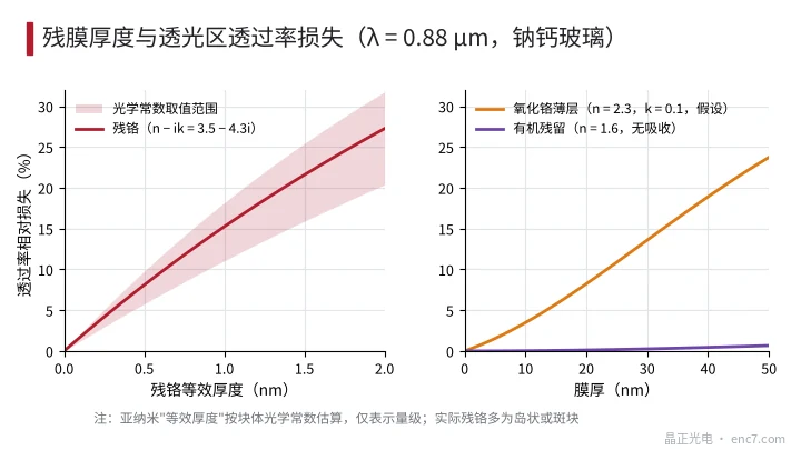
Residual chrome. Chrome left by incomplete etching — even an “equivalent thickness” of only a fraction of a nanometre (averaged over area) — absorbs substantially. Using bulk optical constants (n − ik taken from 3.2 − 3.3i to 4.2 − 4.4i) and a thin-film transfer-matrix calculation, each 0.1 nm of equivalent thickness loses about 1.2%–2.1% at λ = 0.88 μm; 0.2 nm loses about 3.4%, and 1 nm reaches 11%–18% (see Figure 2). Chrome at sub-nanometre thickness is in fact islands or patches, so bulk constants give only the order of magnitude, but that is enough to show that residual chrome invisible to the eye can already consume several percentage points.
Thin oxide and developer residue. Chromium oxide has a high refractive index; assuming n = 2.3 and k = 0.1, 5 nm loses about 1.5% and 10 nm about 3.5%, mainly from increased interface reflection. An organic film left after development (n about 1.6, essentially non-absorbing in the near infrared) acts only as a thin-film interferometer: about 0.1% at 20 nm and about 0.7% at 50 nm. When uniform the effect is small; when uneven it produces scatter and local differences.
Water marks and cleaning residue. Spots of salt or organic matter left after drying lose light mainly by scatter. Estimated as “covered area × local loss”: 2% of the area at a local loss of 50% gives an average drop of 1%. The trouble is that the distribution is uneven.
Transmittance and OD together set the light-to-dark ratio and the modulation depth
Let the clear-area transmittance be T_t and the chrome-area transmittance T_o = 10^(−OD) (OD referred to air). The disc’s own light-to-dark ratio and pattern modulation depth are
C = T_t / T_o = T_t·10^OD, M = (C − 1)/(C + 1) ≈ 1 − 2·10^(−OD)/T_t
The DC component of the signal is proportional to D·T_t + (1 − D)·T_o and the fundamental amplitude to T_t − T_o, where D is the transmitting duty cycle. Using the example data of Figure 1:
| T_t | OD | Light-to-dark ratio C | Modulation depth M | Amplitude (relative to bare glass) |
|---|---|---|---|---|
| 91.8% (bare soda-lime glass) | 3 | 918 | 0.9978 | 1.000 |
| 87.3% (with residual film) | 3 | 873 | 0.9977 | 0.950 |
| 87.3% | 2 | 87 | 0.977 | 0.950 |
| 93.2% (fused silica) | 3 | 932 | 0.9979 | 1.015 |
The conclusion is clear: OD sets the floor of the modulation depth; once OD ≥ 2 the modulation depth is already above 0.97, and raising OD further brings little gain. Clear-area transmittance enters the signal amplitude almost one-to-one, yet affects the modulation depth only at the order of 1/T_t. So “contrast is acceptable” does not mean the signal is large enough. Non-uniform transmittance along a track appears as an amplitude variation once per revolution; if the loss falls only in the detection field of A or of B, it also produces offset and amplitude mismatch (for the effect of local obstruction, see the article on quantitative contamination in this library).
The reference for OD must also be watched: if OD is referred to bare glass of the same type, the absolute transmittance of the chrome area is T_glass·10^(−OD) and the light-to-dark ratio becomes (T_t/T_glass)·10^OD.
Measurement methods and acceptance criteria
Large-area witness region. Leave an unchromed clear area outside the pattern and measure it with a spectrophotometer at the operating wavelength (matching the light source within 850–950 nm), referred to air, to obtain the absolute transmittance. The theoretical value for soda-lime glass is about 91.8%; a clearly lower measured value indicates residual film. The method is simple and reliable, but the cleaning and etching conditions of the witness region are not identical to those of the graduated area.
Micro-photometry in the graduated area. Under a microscope, measure directly inside a slit with a photometry aperture smaller than half the clear slit width; take the reference beam through the same optical path in an unchromed region. When the slit is only a few micrometres wide, edge diffraction makes the reading low; compare against a reference specimen of the same pitch.
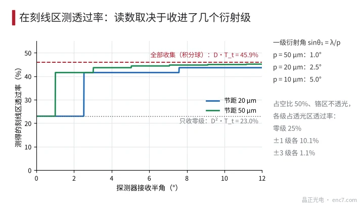
Large-area measurement in the graduated area. When the spot covers many periods the reading depends on the acceptance angle. At 50% duty cycle and an opaque chrome area, collecting everything (integrating sphere) gives D·T_t = 45.9%; collecting only the zero order gives D²·T_t = 23.0%, because the zero order accounts for only 25% of the clear-area light energy and the ±1 orders account for 10.1% each. The first-order diffraction angle satisfies sinθ_1 = λ/p: about 1.0° at a pitch of 50 μm, about 2.5° at 20 μm and about 5.0° at 10 μm. The acceptance half-angle of a collimated instrument is often smaller than this angle (see Figure 3).
Acceptance criteria should state: wavelength, reference (air or bare glass), measurement location (witness region or graduated area), collection method (integrating sphere or collimated), and uniformity along the reading track (maximum-minus-minimum divided by the mean).
Engineering points
- Accept clear-area transmittance on an absolute basis: a soda-lime-glass witness region should be close to 91.8%, and a shortfall of 2 percentage points or more should trigger a check for residual chrome and cleaning residue.
- Once OD ≥ 2 the modulation depth is insensitive to OD; to raise the signal, work on the clear area: keep residual chrome below a sub-nanometre equivalent thickness, and if necessary choose fused silica or apply an anti-reflection coating in the clear area.
- Each 0.1 nm of equivalent residual-chrome thickness loses about 1%–2%; OD and visual inspection alone will not find it — transmittance must be measured at the operating wavelength.
- Large-area transmittance measurements in the graduated area must use an integrating sphere or a sufficiently large acceptance angle; on a fine pitch a collimated instrument collects only the zero order and the reading is roughly halved.
- Uniformity matters more than the mean: a transmittance difference along the track becomes an amplitude variation once per revolution, and a difference between the A and B detection fields becomes an offset.
Summary
The signal ceiling of a transmissive encoder disc is set by clear-area transmittance: reflection at the two glass surfaces first removes about 8%, then residual chrome, oxide, developer residue and water marks remove several more percentage points, often unevenly distributed. OD governs modulation depth and transmittance governs amplitude; at acceptance both must be measured at a stated wavelength, reference and collection method.
Translated from the ENC7 Chinese technical library (article 0276). Read the Chinese original. Need a disc built to your drawing? Request a quote or see our custom encoder discs.
© Langfang Jingzheng Optoelectronic Technology Co., Ltd. All rights reserved. This article was created with AI assistance.