Encoder-disc terminology
Diffraction Efficiency: How Energy Is Shared Among Orders
Diffraction efficiency says how much of the incident light enters a given order. This article distinguishes absolute and relative efficiency, shows that duty-cycle and groove-depth errors affect ±1 only to second order while zero and even orders are more sensitive, gives three mappings from efficiency to signal amplitude, and describes order-by-order power-meter measurement, self-checks and duty-cycle inversion.
Two batches share the same drawing and both pass line-width under the microscope, yet in the same readhead their signal amplitudes differ by more than ten percentage points. Line width measures “what the lines look like”; the readhead cares “where the light went”. The quantity that describes the latter is diffraction efficiency: the fraction of incident power that enters order m. How groove depth is designed to null the zero order is covered elsewhere in this library; this article covers efficiency definitions, error sensitivity, the link to signal amplitude, and measurement.
Definition: absolute efficiency, relative efficiency and conservation
Order-m diffraction efficiency has two definitions:
η_m = P_m / P_in η_m,rel = P_m / P_ref
where P_m is the power in order m, P_in the incident power, and P_ref a reference power: for transmission the transmitted power through an unpatterned region of the same glass, for reflection the reflected power from a flat mirror of the same coating. Relative efficiency removes glass-surface reflection and other losses unrelated to the grating. For uncoated glass at normal incidence each surface reflects about 4%, so the two definitions differ by about 8%; the report must state which. Also state whether a single order or the ±1 sum is meant.
For a binary grating with only two states in the period (fraction D), under the scalar thin-grating approximation:
- Amplitude grating (D = clear fraction): η_0 = D², η_m = sin²(πmD)/(π²m²)
- Phase grating (D = step fraction, φ = phase difference): η_0 = 1 − 2D(1 − D)(1 − cosφ), η_m = 4·sin²(φ/2)·sin²(πmD)/(π²m²)
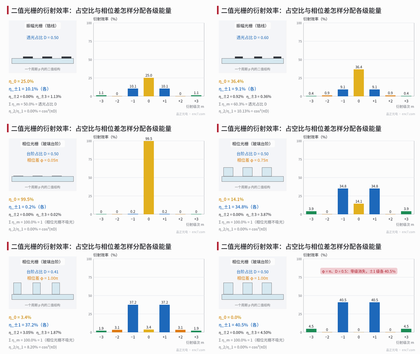
At D = 0.5 an amplitude grating has zero order 25%, ±1 each 10.1%, ±3 each 1.13%; a phase grating with φ = π has zero = 0, ±1 each 40.5%, ±3 each 4.5%, and all even orders zero.
By Parseval’s theorem the sum of the efficiencies equals the mean of the squared modulus of the transmittance function: for an amplitude grating Σ η_m,rel = D, for a phase grating Σ η_m,rel = 1. That is the most useful self-check in measurement.
Error sensitivity: ±1 affected only to second order
In both grating types ±1 contain the factor sin²(πD); a phase grating also has sin²(φ/2). Writing duty-cycle deviation δ = D − 0.5 and relative groove-depth error ε (φ = π(1 + ε)),
η_±1 / η_±1,ideal = cos²(πδ)·cos²(πε/2) ≈ 1 − (πδ)² − (πε/2)²
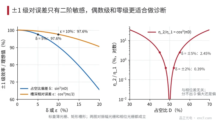
So δ = 5% or ε = 10% each cuts ±1 by only about 2.4% (see Figure 2 left). Worked values for a φ = π phase grating:
| D | ε | η_0 | η_±1 (each) | η_±2 (each) |
|---|---|---|---|---|
| 0.50 | 0 | 0 | 40.5% | 0 |
| 0.50 | 10% | 2.45% | 39.5% | 0 |
| 0.45 | 0 | 1.00% | 39.5% | 0.97% |
| 0.45 | 10% | 3.42% | 38.6% | 0.94% |
| 0.40 | 0 | 4.00% | 36.7% | 3.50% |
For an amplitude grating at D = 0.45, η_0 = 20.25%, η_±1 = 9.88%, η_±2 = 0.24%.
The conclusion: ±1 efficiency is insensitive to process deviation, so using it to judge process drift is dull; zero and even orders, which change from zero or from first order, are the good diagnostic quantities. For any binary grating
η_2 / η_1 = cos²(πD) ≈ (πδ)²
independent of phase difference and grating type: 0.39% at δ = 2%, 2.45% at δ = 5% (see Figure 2 right).
How signal amplitude tracks efficiency
The factor that maps an efficiency change into signal amplitude depends on the reading method.
Imaging (amplitude grating). Under geometric projection the Fourier coefficients of disc and index-grating transmittance are a_m and b_m; the signal fundamental amplitude is 2·|a_1|·|b_1| = 2·√(η_1,disc·η_1,index), so it tracks the square root of disc η_1.
Interferential. Each beam is diffracted once on the disc and once on the second grating; with symmetric arms the AC amplitude is about 2·P·η_1,disc·η_1,second·V (V = visibility) and tracks disc η_1 linearly; if the path diffracts twice on the disc it tracks η_1².
So a 5% drop in disc η_1 cuts an imaging signal by about 2.5%, a single-diffraction interferential signal by about 5%, and a double-diffraction one by about 10%. Also, modulation depth is insensitive to ±1 asymmetry: 2·√(η₊·η₋)/(η₊ + η₋) is still 0.994 at η₊/η₋ = 0.8, but zero-order leakage and stray light into the detector raise the DC component directly.
Measurement: order-by-order with a power meter
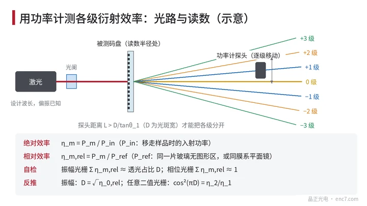
- Source and spot: use collimated light near the design wavelength; the spot must cover tens of periods or more and lie wholly inside the track; record whether polarisation is parallel or perpendicular to the lines; when pitch is only a few wavelengths, measure both polarisations.
- Geometry: set the incidence angle to the readhead’s actual angle; the detector aperture must fully collect a single order, at distance L > D/tanθ_1 (D = spot width). At p = 20 μm and D = 1 mm, L must exceed about 23 mm.
- Reference: measure P_in or P_ref with the same head and the same range.
- Order-by-order reading: measure orders 0, ±1, ±2, ±3, subtracting dark current and ambient light.
- Self-check: compare Σ η_m,rel with D or 1; the missing part comes from unmeasured high orders, scatter and absorption; if ±1 are clearly asymmetric, first check incidence angle and groove-profile asymmetry.
- Inversion: for an amplitude grating D = √η_0,rel; for a binary grating |δ| from η_2/η_1; for a phase grating then φ from 1 − cosφ = (1 − η_0)/(2D(1 − D)). Example: at D = 0.47, ε = +6%, η_0 = 1.24%, η_1 = 39.8%, η_2 = 0.35%, inversion gives |δ| = 3.0% and φ = 169.2° or 190.8°. Whether the groove is shallow or deep needs a second wavelength or a profilometer.
Common errors: coherent laser multiple reflections between the two glass faces make transmittance vary with local thickness; for uncoated glass under ideal parallelism and full coherence it can swing between about 0.85 and 1 times its maximum—choose a source whose coherence length is much less than 2n·t (e.g. an LED plus a 10 nm narrowband filter, coherence length about 77 μm); zero order may be two or three orders of magnitude below ±1, so probe linearity and attenuator calibration must be included; at the read radius pitch varies with radius—at 1 mm radial spot width and r = 20 mm pitch changes by 5%—orders broaden slightly and the probe aperture needs margin.
Engineering points
- State the efficiency definition in the specification: absolute or relative, single order or ±1 sum, wavelength, incidence angle, polarisation, spot size and position.
- ±1 is only second-order sensitive to duty cycle and groove depth; δ = 5% or ε = 10% each cut about 2.4%—process monitoring must also record zero and ±2.
- η_2/η_1 = cos²(πD) quickly estimates duty-cycle deviation; at δ = 2% it is only 0.39%, so measurement needs dynamic range of order 10⁻³.
- Before converting efficiency to signal amplitude, confirm the reading method: imaging tracks √η_1, single-diffraction interferential tracks η_1, double diffraction tracks η_1².
- Use Σ η_m conservation and ±1 symmetry as measurement self-checks; when the deviation is large, check the optical path first, then the disc.
- For transmission measurement use a short-coherence source, or take a reference near the measurement point, to avoid ripples from two-face interference in the glass.
Summary
Diffraction efficiency must first state its definition. ±1 efficiency is only second-order sensitive to duty cycle and groove depth—good for gauging signal potential, poor for process monitoring; zero and even orders are more sensitive, and η_2/η_1 = cos²(πD) can invert duty cycle. How an efficiency change maps into signal amplitude depends on the reading method; with order-by-order power-meter measurement, conservation self-checks and a short-coherence source, the result is trustworthy.
Translated from the ENC7 Chinese technical library (article 0262). Read the Chinese original. Need a disc built to your drawing? Request a quote or see our custom encoder discs.
© Langfang Jingzheng Optoelectronic Technology Co., Ltd. All rights reserved. This article was created with AI assistance.