Industry applications in depth
Direct-Drive Swivel Heads: Large-Bore Disc Heat and Tool-Tip Error
The encoder disc of a direct-drive swivel head is fitted on a Ø150 mm hollow shaft; motor heating produces a temperature difference across the two sides of the hub. This article estimates, with the first-order formula for a linear gradient, a tool-tip error of about 6.8 μm for a steel hub with rigid bonding at a 10 K temperature difference, and about 1.9 μm for flexibly bonded borosilicate glass, and gives recommendations on the substrate, the hub and the readhead arrangement.
The direct-drive swivel head of a five-axis machine tool is driven directly by a torque motor, with no reducer, and what the encoder reads is the swivel angle itself. The tool tip lies at a distance L = 200 mm outside the swivel axis, so an angular error multiplied by the swivel length is a displacement of the tool tip: 1″ corresponds to 0.97 μm. After the motor reaches full load it generates heat; heat enters the hub from the stator side, and a temperature difference appears across the two sides of the hub. A large-bore encoder disc fitted on a Ø150 mm hollow shaft, with a reading radius of about 85 mm, is not insensitive to this temperature difference.
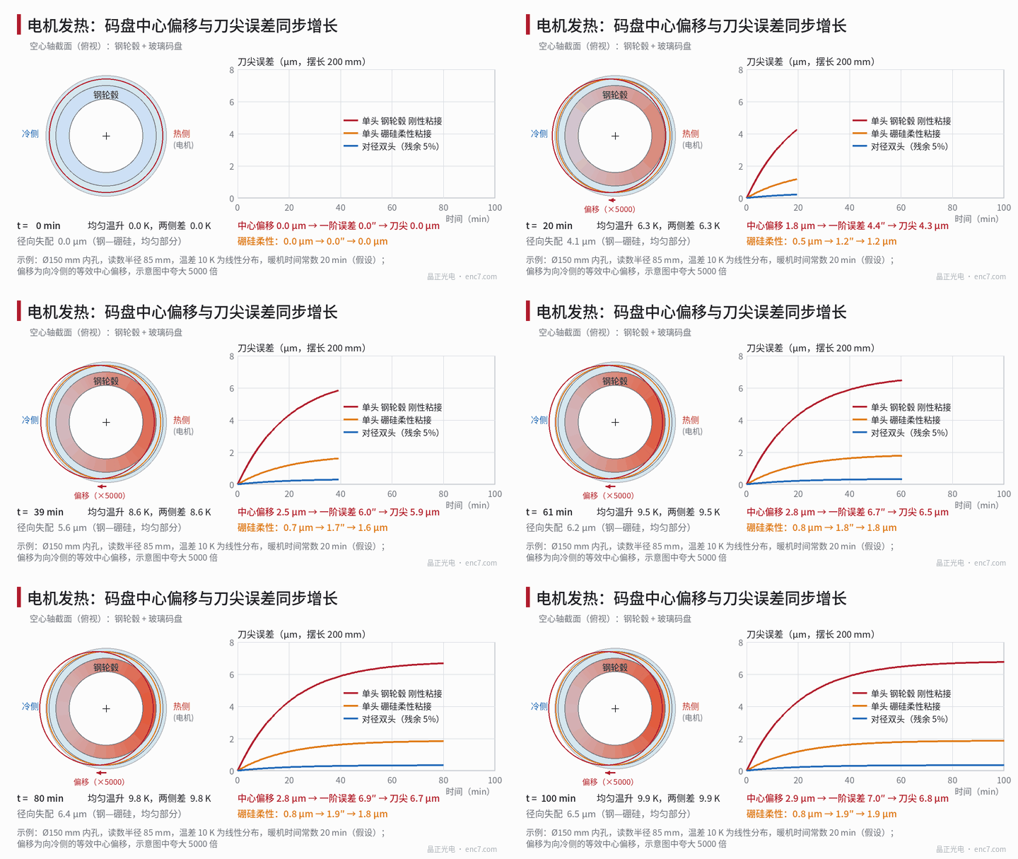
The model: the uniform part and the linear gradient
The temperature field can be split into two parts. A uniform temperature rise scales all dimensions in the same proportion, does not change the graduation angles, and only produces a radial mismatch Δα·ΔT·r_b between the hub and the glass. In the example the hub is taken as structural steel (about 12×10⁻⁶/K), the bonding radius as 75 mm and the temperature rise as 10 K: for soda-lime, borosilicate and fused-silica encoder discs the mismatch is about 2.3, 6.5 and 8.6 μm respectively, and is absorbed by the adhesive layer or the fitting clearance.
It is the linear gradient that produces an angular error. Suppose a 10 K temperature difference across the two sides of the hub is distributed linearly along the 150 mm diameter, so G = 10 K ÷ 0.15 m = 66.7 K/m. A free body in a linear temperature field has no thermal stress, and the change in graduation angle is
Δψ = (α·G·r / 2)·sinψ,equivalent centre shift e = α·G·r² / 2
toward the cold side, where r is the reading radius. The question is whose α to take. The encoder disc is connected to the hub by an adhesive layer, and there are two limits: with flexible bonding the disc deforms almost freely according to its own temperature field, so α is that of the glass; with rigid bonding the hub is thick and stiff, the disc is carried with it, and α is that of the hub. Reality lies between the two, depending on the stiffness of the adhesive layer and the bond pattern. The figures below are order-of-magnitude estimates and should be confirmed by finite-element analysis and a warm-up test.
Worked example: 10 K temperature difference, r = 85 mm
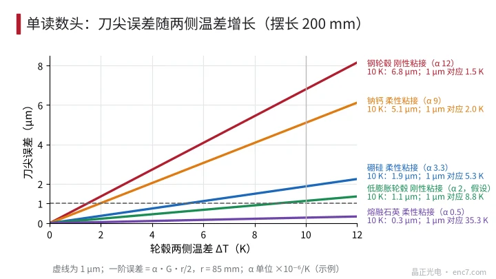
| Arrangement (single readhead) | α (×10⁻⁶/K) | Centre shift | First-order angular error | Tool tip (200 mm) |
|---|---|---|---|---|
| Steel hub, rigid bonding | 12 | 2.9 μm | 7.0″ | 6.8 μm |
| Soda-lime glass, flexible bonding | 9 | 2.2 μm | 5.3″ | 5.1 μm |
| Borosilicate glass, flexible bonding | 3.3 | 0.79 μm | 1.9″ | 1.9 μm |
| Fused silica, flexible bonding | 0.5 | 0.12 μm | 0.29″ | 0.28 μm |
| Low-expansion hub (assumed α about 2), rigid bonding | 2 | 0.48 μm | 1.2″ | 1.1 μm |
With rigid bonding, even a very good glass is of no use: the error is determined by the α of the hub. Taking a tool-tip budget of 1 μm, the temperature differences across the two sides that a single head can allow are: 1.5 K for a steel hub with rigid bonding, 5.3 K for flexible bonding of borosilicate, and 8.8 K for a low-expansion hub (Figure 3). This differs from a continuously rotating shaft: the swivel head moves only through a limited angle, the temperature field is fixed to the housing, and the encoder disc cannot average it into axisymmetry; the error is a function of the swivel angle and changes with load and the warm-up process.
Readhead arrangement
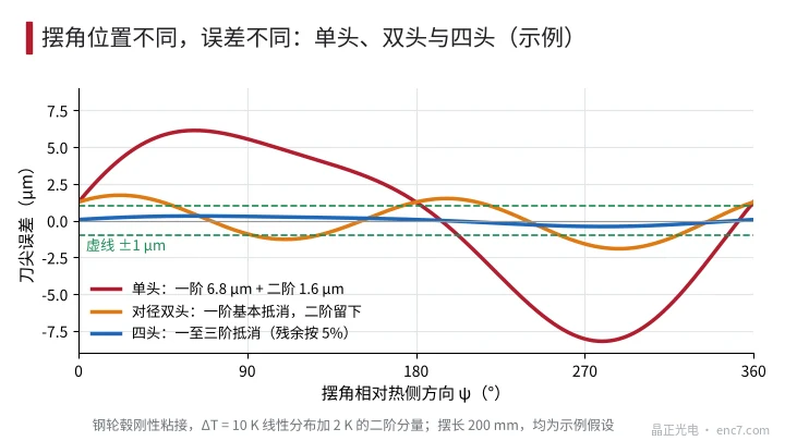
Diametrically opposed dual readheads average out the first-order term (and all odd orders); taking the residual as 5%, the tool tip is about 0.34 μm at 10 K. The actual temperature field, however, will not be purely linear. If a 2 K second-order component is superimposed, the estimate α·T_m/(m+1) gives about 1.65″ for a steel hub with rigid bonding, or 1.6 μm at the tool tip. Dual heads cannot cancel even orders; only four equally spaced readheads can remove the first through third orders (Figure 2). Tangential thermal drift of the readhead brackets is not affected by the number of readheads; it has to be handled by symmetrical mounting and thermal isolation. A related article on direct-drive rotary tables in this library discusses this in detail.
Substrate and hub design
- Reducing the temperature difference is more direct than changing the material: distribute cooling channels uniformly around the circumference of the hub, and arrange the heat sources symmetrically, so that the temperature field is close to axisymmetric; the smaller the linear component G, the smaller the error.
- Hub material: choose a low-expansion alloy (coefficient of thermal expansion of order 1~5×10⁻⁶/K), and check strength, magnetic permeability and machinability; leave a compliant layer between the hub and the encoder disc.
- Bonding: use an elastic adhesive, uniformly distributed spots or a continuous thin layer, so that the glass is not carried along by the expansion of the hub.
- Stress: for a steel hub and borosilicate glass with a 10 K rise, the upper bound under rigid constraint is about E·Δα·ΔT = 63 GPa × 8.7×10⁻⁶ × 10 K ≈ 5.5 MPa; at a 40 K rise it is about 22 MPa, already of the same order as the common design strength of glass (tens of MPa), which is another reason not to bond rigidly.
- Compensation: mount a temperature sensor on each of the two diametrically opposite sides of the hub; the error is proportional to ΔT and can be compensated with a measured coefficient.
Engineering points
- First convert the angle into tool-tip displacement: at a 200 mm swivel length, 1″ ≈ 0.97 μm; a 1 μm centre shift of a large-bore encoder disc is about 2.4″ at r = 85 mm.
- Use e = α·G·r²/2 to estimate the effect of an asymmetric temperature difference; α is taken between that of the glass and that of the hub, and the stiffness or compliance of the bond must be known.
- The temperature field of a swivel head is fixed to the housing and is not averaged by rotation; the first-order error is a function of the swivel angle.
- With a single head and a steel hub with rigid bonding, only about 1.5 K of temperature difference is allowable; diametrically opposed dual heads should be used, and even orders should be considered, with four heads if necessary.
- Reducing the temperature difference, symmetrical cooling and flexible bonding take priority over changing the substrate; a low-expansion hub can bring the error of rigid bonding down to the 1 μm order.
- After warm-up, perform a swivel-angle positioning calibration, record the temperature difference across the two sides, and check the slope of error versus temperature difference.
In brief
Thermal error of the encoder disc on a direct-drive swivel head comes from an asymmetric temperature field: the first-order angular error is α·G·r/2, and multiplied by the swivel length it is the tool-tip error. In the example, at a 10 K temperature difference a steel hub with rigid bonding gives about 6.8 μm, flexible bonding of borosilicate about 1.9 μm, and diametrically opposed dual heads can reduce the first-order term to about 0.3 μm. Only by using a smaller temperature difference, flexible bonding, a low-expansion hub and diametrically opposed dual readheads together can the thermal error be held below 1 μm.
Translated from the ENC7 Chinese technical library (article 0768). Read the Chinese original. Need a disc built to your drawing? Request a quote or see our custom encoder discs.
© Langfang Jingzheng Optoelectronic Technology Co., Ltd. All rights reserved. This article was created with AI assistance.