Custom discs
Distance-Coded Reference Marks on Encoder Discs: Spacing, Homing

Distance coding on a disc requires the spacings of K marks to differ pairwise by at least Δ and to add up to exactly one revolution. This article derives the closure condition, the maximum number of marks and the maximum homing angle, shows that an interleaved arrangement reduces the homing angle to about 2N/K + Δ, and gives a worked example with 32 marks on a 2048-line disc and a maximum homing angle of 23.0°.
When an incremental disc has only one reference mark, finding it after power-up can take up to a full revolution in the worst case. Distance-coded reference marks are well established on linear scales (principle and linear design are covered by the distance-coding articles in this library); transferred to a disc, they let the motor know the absolute angle after turning only a dozen or two dozen degrees. The biggest difference between a disc and a linear code strip is that a disc has no ends: all spacings must add up to exactly one full revolution, and the last mark must join up with the first. This article derives the spacings, number of marks and maximum homing angle under this closure condition.

Coding rule and closure condition
The unit is the signal period of the incremental track; one revolution has N periods (N = 2048 for a 2048-line disc). K reference marks are placed around the circumference, with spacings g_1 … g_K between adjacent marks, subject to:
- All spacings are pairwise different and any two differ by at least Δ periods, so that they can still be identified with a counting error below Δ/2 (for the choice of Δ see the article on distance-coding error tolerance in this library; Δ = 3 corrects ±1 period);
- The smallest spacing is not less than g_min, so that two marks never appear in the reading window at the same time;
- Closure: Σ g_i = N.
The simplest choice is an arithmetic progression: g_i = D + (i − 1)·Δ. The closure condition is
K·D + Δ·K(K − 1)/2 + R = N
where R is the remainder (0 ≤ R < K). If R is not zero, add 1 period to each of the R largest spacings: they still differ from each other by Δ and from the smaller group by Δ + 1, so the ability to distinguish them is not reduced. From D ≥ g_min follows the maximum number of marks: K is the largest value satisfying ⌊(N − Δ·K(K − 1)/2)/K⌋ ≥ g_min.
After passing any two adjacent marks, the measured spacing identifies the segment and hence the absolute angle of the mark just passed. In forward rotation the mark just passed is the end mark of that segment, in reverse rotation its start mark, so decoding also needs the A/B direction. Eccentricity affects the spacing count only through the radius difference between reference track and incremental track: with 20 μm eccentricity and track radii of 15 mm and 14.2 mm, the differential amplitude is only about 0.02 periods and can be neglected.
Maximum homing angle: the arrangement order is key
Starting from any position, two marks must be seen; the worst case is having just missed a mark, so two adjacent spacings have to be traversed. The maximum homing angle is
T_max = max(g_i + g_(i+1))
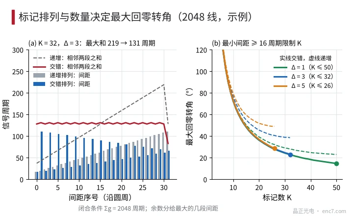
With the spacings arranged in increasing order, the two largest are adjacent and T_max ≈ 2N/K + (K − 2)·Δ. This first decreases and then increases with K, with a minimum near K = √(2N/Δ).
Arranging the spacings interleaved as “smallest, largest, second smallest, second largest …” makes the sums of adjacent pairs almost equal, T_max ≈ 2N/K + Δ. The mean of all adjacent sums is exactly 2N/K, so this is already close to the lower bound, and the larger K the better, limited only by g_min. In the interleaved arrangement g_i + g_(K+1−i) is constant, so every second mark is exactly evenly spaced — the same structure as the “fixed mark + variable mark” scheme of linear distance coding; on a circle it satisfies the closure condition automatically.
Worked example for 2048 lines
Example parameters: at r = 15 mm the signal period is about 46.0 μm; g_min is taken as 16 periods (about 0.74 mm, including the length of the reference-mark pattern, the reading window and margin; an assumed value); Δ = 3.
- Maximum number of marks: for K = 32, D = ⌊(2048 − 1488)/32⌋ = 17 ≥ 16; for K = 33, D is less than 16; hence K = 32.
- Remainder R = 2048 − 32 × 17 − 1488 = 16; add 1 to each of the 16 largest segments. The spacings are 17, 20 … 62 (16 segments) and 66, 69 … 111 (16 segments), total 2048.
- Interleaved arrangement: 17, 111, 20, 108, 23, 105 …, 62, 66. Every second mark is 128 periods (22.5°) apart.
- Maximum homing: 108 + 111 = 219 periods (38.5°) for the increasing order, 111 + 20 = 131 periods (23.0°) for the interleaved order. With uniformly distributed start positions the mean homing angles are about 19.7° and 15.9° respectively, against a maximum of 360° and a mean of 180° for a single reference mark.
Effect of changing Δ (g_min = 16 periods):
| Δ | Correctable error | Number of marks K | Min./max. spacing | Max. homing (increasing) | Max. homing (interleaved) | Mean homing (interleaved) |
|---|---|---|---|---|---|---|
| 1 | None | 50 | 16 / 66 | 23.0° | 14.6° | 10.4° |
| 3 | ±1 period | 32 | 17 / 111 | 38.5° | 23.0° | 15.9° |
| 5 | ±2 periods | 26 | 16 / 142 | 49.0° | 28.7° | 19.3° |
Layout and decoding notes
The centres of the reference marks must fall on an integer number of signal periods and be aligned with the incremental lines on the same mask, so that after the reference pulse is gated to one quadrant of the incremental signal the spacing count is an integer. If the count uses x4 decoding, both the spacings and Δ are multiplied by 4. The decoding table has only K entries: spacing value → segment number → angles of start and end mark. If the measured spacing differs from the nearest table value by more than Δ/2, an error should be reported, and the result can be cross-checked by passing a third mark.
Engineering checklist
- Closure condition K·D + Δ·K(K − 1)/2 + R = N; adding the remainder R to the R largest spacings does not affect identification.
- The number of marks is set by the minimum spacing: g_min includes the mark pattern and the reading window; for 2048 lines, g_min = 16 periods and Δ = 3, K = 32.
- Always use the interleaved arrangement: the maximum homing angle drops from 2N/K + (K − 2)Δ to about 2N/K + Δ, in the example from 38.5° to 23.0°.
- The interleaved arrangement is equivalent to evenly spaced fixed marks with variable marks inserted between them; in the example the fixed marks are 128 periods apart.
- Δ = 3 corrects counting errors of ±1 period, at the cost of increasing the homing angle from 14.6° to 23.0°.
- Decoding must use the A/B direction to tell whether the mark just passed is a segment start or end; align the mark centres with the incremental lines on the same mask.
Summary
Distance coding on a rotary disc must satisfy three conditions: spacings differing pairwise by at least Δ, a minimum spacing of at least g_min, and a total of exactly one revolution. The minimum spacing determines the number of marks; the number of marks and the arrangement order determine the maximum homing angle. The interleaved arrangement brings the sum of adjacent spacings close to the mean 2N/K, already near the lower bound for a circular layout. A 2048-line disc with 32 marks has a maximum homing angle of about 23° — more than an order of magnitude less than with a single reference mark.
Translated from the ENC7 Chinese technical library (article 0306). Read the Chinese original. Need a disc built to your drawing? Request a quote or see our custom encoder discs.
© Langfang Jingzheng Optoelectronic Technology Co., Ltd. All rights reserved. This article was created with AI assistance.