Competing technologies and trends
Domestic encoder production: the technology chain from disc to chip
The resolution of an optical encoder is written in the chip specification, but accuracy and reliability are decided jointly by the disc, the read optics, the optoelectronic chip, the interpolation algorithm, calibration and testing. This article gives key figures for each link and, with a single-turn error-budget example, shows that the bottleneck is often in assembly and calibration.
Talk of domestic encoder production often centres on “can we make the chip ourselves” and “can we reach 23 bits”. Those points matter, but an encoder is a chain: the disc sets the foundation of the signal, the read optics determine the signal quality, the chip and the algorithm turn the signal into numbers, and calibration and testing make the accuracy real and demonstrate it. If any link is weak, the effort spent on the earlier ones is wasted. This article takes the links in order, gives the key figures for each, and uses an error budget to show how much each link contributes.
The disc and the read optics
First link: the disc
The disc is the length standard of the whole chain. The key figures include graduation error, line-width uniformity, optical density of the opaque layer, quality of the line edges, accuracy of the centring datum, and defect density.
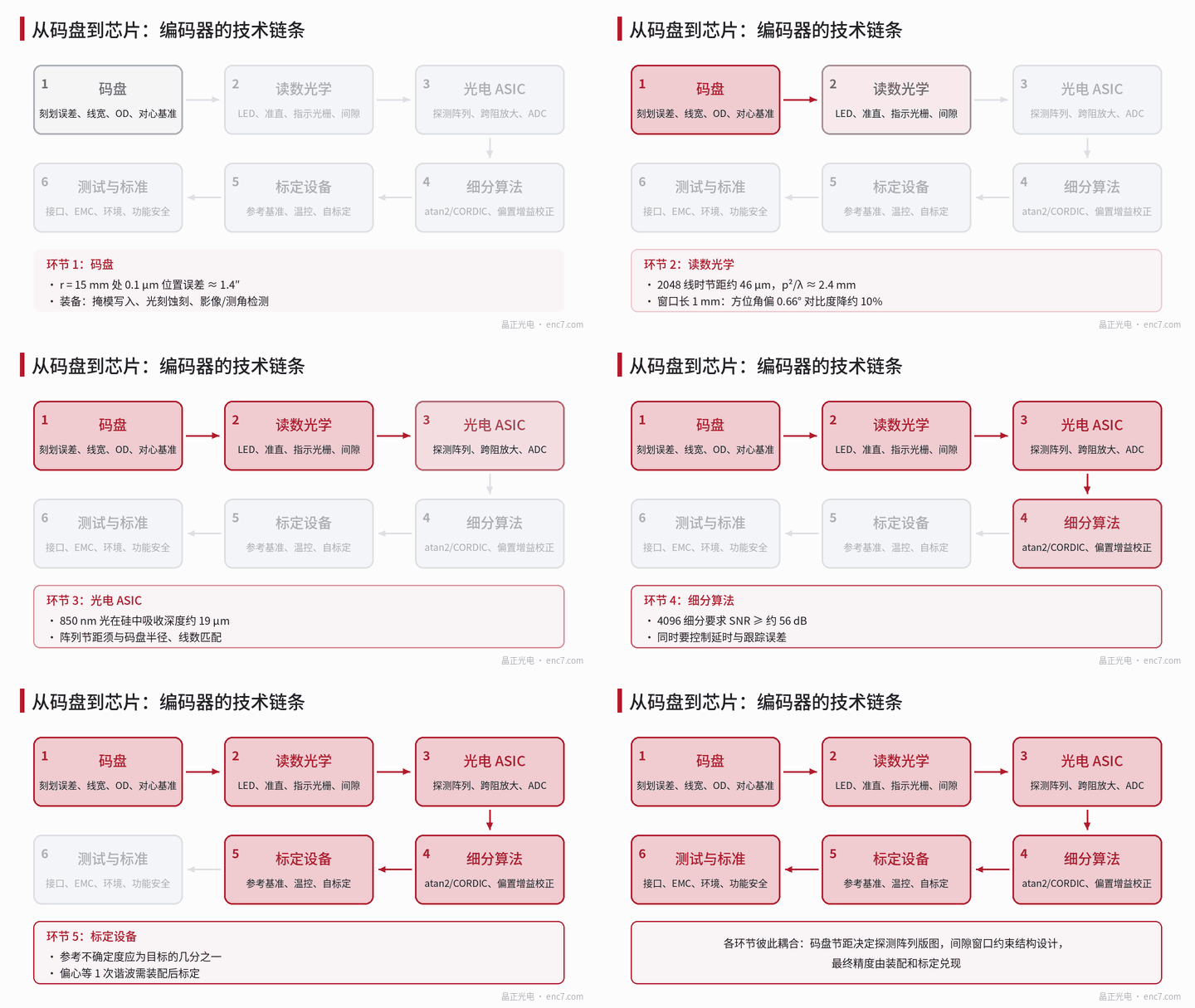
Graduation error becomes an angular error directly: Δθ = Δx / r. At a read radius r = 15 mm, a position error of 0.1 μm is about 1.4″. At the same radius the pitch of a 2048-line disc is about 46 μm and the line width about 23 μm. When the optical density of the chrome layer reaches OD 3, leakage is only 0.1%. Behind these numbers lie photomask writing, photolithography, etching and measuring capability: the positional accuracy of the master sets the ceiling for every replica, and measuring capability in turn decides whether that accuracy can be demonstrated.
Second link: the read optics
The read optics include the LED, the collimating lens, the index grating or the detector array, and the gap and alignment between them and the disc.
- Gap window: imaging (scanning) readout requires the gap to be much smaller than p²/λ. At a pitch of 46 μm and a wavelength of 0.88 μm this is about 2.4 mm; at a pitch of 20 μm it is only about 455 μm.
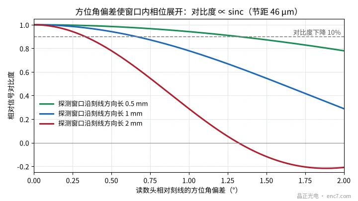
- Azimuth alignment: when the readhead is rotated by an angle θ relative to the graduation lines, the phase is unwound across a detection window of length L along the lines, and the contrast falls as sinc(π·θ·L/p). With p = 46 μm and L = 1 mm, contrast has fallen by about 10% at θ ≈ 0.66°; at L = 2 mm the tolerance is halved (see Figure 2).
- Source thermal drift: the peak wavelength of a near-infrared LED drifts by about 0.2–0.3 nm/K, and the optical output falls as temperature rises, so constant-light control is needed.
The optoelectronic chip and the interpolation algorithm
Third link: the optoelectronic ASIC
The chip integrates a photodiode array, transimpedance amplification, offset and gain correction, an ADC, interpolation and the interface. It faces several problems that differ from those of an ordinary mixed-signal chip:
- Photoelectric conversion efficiency: the absorption depth of 850 nm light in silicon is about 19 μm, thicker than the active layer of many standard processes, so collection efficiency depends on the epitaxial-layer thickness and the device structure.
- Dark current and temperature: the dark current of a silicon photodiode roughly doubles for every 8–10 °C rise in temperature, and at high temperature it affects the offset of small signals.
- Co-design with the disc: in array readout the detector pitch must match the disc pitch at the read radius, so the chip layout is in fact designed for a particular radius and line count, and a change of disc specification often means a change of layout.
Fourth link: the interpolation algorithm
12-bit interpolation means 4096 divisions per period, and 1 LSB corresponds to 2π/4096 ≈ 1.53×10⁻³ rad of electrical angle. For the noise not to exceed 1 LSB (rms), with σ_φ = σ_n/A the signal-to-noise ratio A/σ_n must be at least about 650 (56 dB). For an ideal 12-bit ADC at full scale, the ratio of sine amplitude to the RMS of the quantization noise is about 77 dB, which leaves some margin. The algorithm must also apply on-line correction of offset, gain and phase, solve for the angle with a look-up table, CORDIC or a tracking loop, and keep latency and tracking error at high speed under control.
Fifth link: calibration equipment and the error budget
Accuracy must finally be demonstrated by measurement. A common rule of thumb is that the uncertainty of the reference standard should be a fraction of the specification under test, so to calibrate an encoder of the ±10″ class one needs an angle-measuring setup of arcsecond grade or better, and a temperature-controlled environment; self-calibration methods can to some extent reduce the dependence on a still more accurate standard.
Worked example: r = 15 mm, 2048 lines, 12-bit interpolation (23-bit output, about 0.15″ per count), estimated error amplitudes for a single readhead are as follows (see Figure 3):
| Error term | Assumption | Amplitude |
|---|---|---|
| Disc graduation error | 0.1 μm | 1.4″ |
| Mounting eccentricity | 1 μm | 13.8″ |
| Shaft radial runout | 0.5 μm | 6.9″ |
| Interpolation error | 1/500 of a period | 1.3″ |
| Thermal drift, noise | assumed values | 0.5″, 0.3″ |
| Combined (root-sum-square) | — | about 15.5″ |
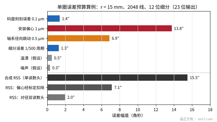
The conclusion is clear: a 23-bit output is about 0.15″ per count, yet the accuracy is dominated by the 13.8″ that comes from 1 μm of eccentricity. After assembly, once the repeatable eccentricity has been calibrated out, about 7.1″ remains; with diametrically opposed dual readheads the first-order terms of eccentricity and radial runout cancel, leaving about 2.0″. Raising the bit count of the chip still further does not change this structure.
Sixth link: testing and standards
For a product to enter servo, robot and safety-related applications, a systematic test capability is needed:
- Interfaces: timing and conformance tests of open protocols such as BiSS and SSI.
- Electromagnetic compatibility: the IEC 61000-4 series, for example electrostatic discharge (−4-2), electrical fast transients (−4-4) and immunity to conducted disturbances (−4-6).
- Environment and mechanics: tests in the IEC 60068-2 series such as vibration (−6), shock (−27) and temperature cycling.
- Functional safety: IEC 61508 and ISO 13849 place requirements on diagnostic coverage and failure analysis of position feedback.
- Life: accelerated life tests with the Arrhenius model are used to estimate LED lumen depreciation and the life of the adhesive layer.
Engineering points
- Draw up the error budget before deciding where to invest: in the example, 1 μm of eccentricity contributes 13.8″, far larger than the 0.15″ counting resolution, so centring and calibration should be settled before the bit count is raised.
- Co-design the disc and the chip: array pitch, read radius and line count must be fixed together, to avoid a chip that can be paired with only one kind of disc.
- Treat master accuracy as the source: at r = 15 mm a graduation error of 0.1 μm is about 1.4″; photomask writing and measuring capability set the ceiling on disc accuracy.
- Leave tolerance for assembly and adjustment: with a detection window 1 mm long the azimuth tolerance is about 0.66°, and the longer the window the tighter the tolerance, so fixtures and process must be able to guarantee it.
- Build measuring capability first: the reference standard, the temperature-controlled environment and the self-calibration method should be in place before the product accuracy target.
- Build the test platform against the standards: EMC, environmental, functional-safety and life tests are all indispensable.
Summary
The encoder technology chain runs from the disc master all the way to the test standards, and the links are coupled to one another: disc pitch determines the chip layout, the gap window constrains the mechanical design, and assembly and calibration decide whether the accuracy can be made real. The error budget shows that the bottleneck is often not the bit count of the chip, but disc accuracy, centring and calibration capability. Quantifying the figures of every link, and co-designing across links, is what it takes to make an encoder truly stable and accurate.
Translated from the ENC7 Chinese technical library (article 0190). Read the Chinese original. Need a disc built to your drawing? Request a quote or see our custom encoder discs.
© Langfang Jingzheng Optoelectronic Technology Co., Ltd. All rights reserved. This article was created with AI assistance.