Specification
Duty Cycle: Why Encoder Disc Lines and Gaps Are Usually 1:1

Disc drawings often state “line width : gap width = 1:1”. The reason: with a 1:1 index grating, a disc that transmits exactly 50% gives the largest AC signal. Away from 1:1 the signal amplitude falls, and when the signal is squared with a fixed threshold the square-wave width shifts too, so the x4 count intervals are no longer uniform. This article uses worked examples to explain the effects of duty cycle and how to inspect it.
Disc drawings often say “line width : gap width = 1:1” or “duty cycle 50%”. Why not 1:2 or 2:1? And what happens if the result is a little off — say the gaps take 55%?
Duty cycle here means the share of one pitch taken by the transmitting gap (for reflective discs, the share of the reflective area). The analysis below assumes a 1:1 index grating and an approximately sinusoidal signal.
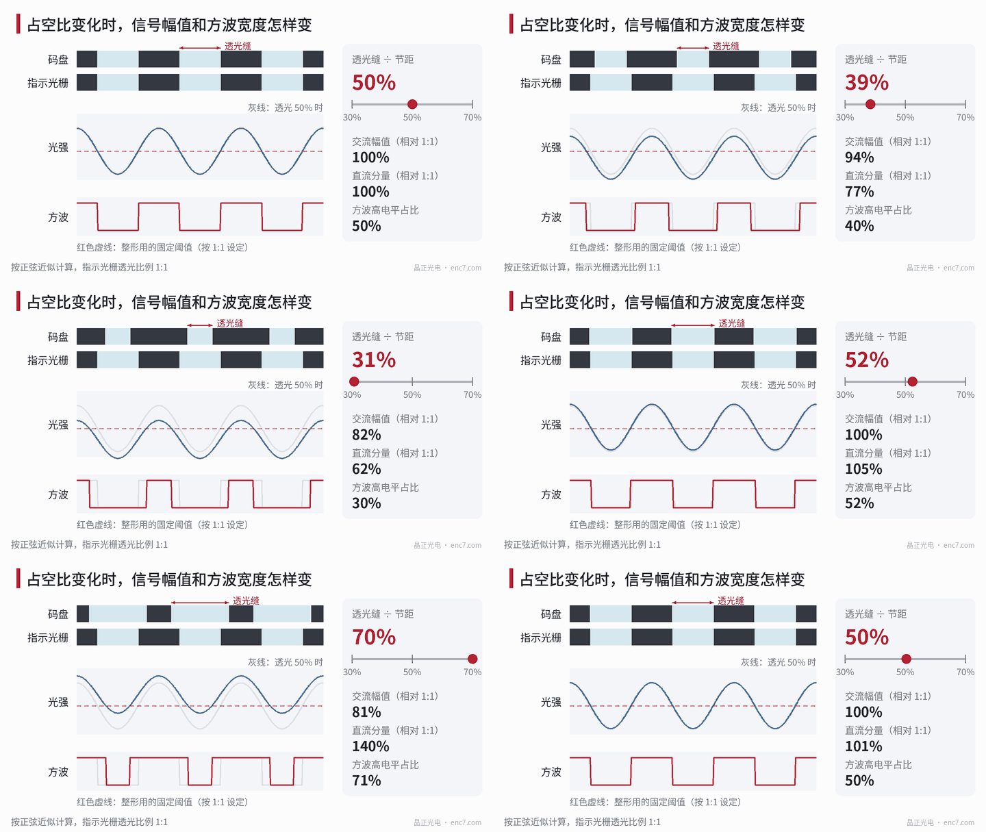
AC signal is largest at 1:1
As the disc turns, its gaps and those of the index grating alternately align and misalign, and the transmitted light goes strong and weak. What actually carries position information is the AC part.
It can be shown that with a 1:1 index grating the amplitude of the fundamental (sinusoidal part) is proportional to sin(π × duty cycle), and the DC part is proportional to the duty cycle:
| Transmitting share | AC amplitude (1:1 = 1) | DC component (1:1 = 1) |
|---|---|---|
| 50% | 1 | 1 |
| 40% or 60% | about 0.95 | 0.8 or 1.2 |
| 30% or 70% | about 0.81 | 0.6 or 1.4 |
So 1:1 is the peak of AC amplitude. A 10-point deviation only reduces amplitude about 5%, which looks small, but it stacks with eccentricity, gap, contamination and other factors and eats into the signal margin.
When it is off: square-wave width shifts
If the squaring circuit uses a fixed threshold set for 1:1, a shifted duty cycle changes the DC component and the square wave’s high-level width shifts with it. Using the sine approximation: at 40% transmitting, the high level occupies about 42%; at 60%, about 58% (Figure 1).
x4 counting counts once on every rising and falling edge of both A and B. Once the square-wave width shifts, the count intervals are no longer uniform. For 2,500 lines, each count is ideally 129.6″; at 40% transmitting the four intervals become about 129.6″, 86.3″, 129.6″ and 172.9″ (Figure 2). If speed is calculated from count intervals, a periodic ripple appears.
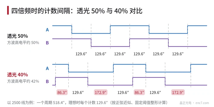
If the circuit compares differentially (A minus A−), the DC component cancels and square-wave width is largely unaffected, but the loss of AC amplitude remains.
Where line-width deviation comes from
Duty-cycle deviation mostly comes from line-width deviation: poorly controlled exposure dose, development or etching makes lines systematically wider or narrower across the whole disc, and line-width error in the mask itself is carried over too.
The same absolute deviation shifts duty cycle more at smaller pitch. Example at radius 20 mm, chrome lines 2.5 μm narrower than design:
- 2,500 lines, pitch about 50.3 μm: transmitting share goes from 50% to about 55%;
- 10,000 lines, pitch about 12.6 μm: transmitting share becomes about 70%.
How to check duty cycle in inspection
- At the read radius, measure line width and pitch with an image measuring instrument and convert to duty cycle. Line width of radial lines varies with radius, so always measure at the specified radius.
- Measure at several evenly spaced positions around the circumference to see whether the whole revolution is consistent.
- Use a consistent edge-detection criterion. Ragged edges and residual chrome make measured values disagree with the actual optical effect.
- After assembly into an encoder, use an oscilloscope to check the high/low time ratio of channel A and the Lissajous figure of A and B.
Summary
1:1 is not a habit but the design point that gives the largest AC signal and the most uniform square wave. With an off-nominal duty cycle, amplitude falls, square waves widen or narrow, and x4 count intervals become uneven. The finer the pitch, the more line-width control matters; inspect at the read radius at multiple points around the full revolution.
Translated from the ENC7 Chinese technical library (article 0018). Read the Chinese original. Need a disc built to your drawing? Request a quote or see our custom encoder discs.
© Langfang Jingzheng Optoelectronic Technology Co., Ltd. All rights reserved. This article was created with AI assistance.