Industry applications in depth
Encoder-triggered line-scan capture: line count, division and pixel size

When a line-scan camera is triggered by an encoder, the line spacing Δy = πD·K/(4N) must equal the object-side transverse pixel size, or circles become ellipses. This article derives the constraints among line count, frequency division, maximum line rate and maximum web speed, works an example with a 100 mm roller diameter and a 10 μm pixel to obtain 7854 lines with fourfold quadrature decoding, and estimates the periodic line-position error caused by encoder eccentricity.
A line-scan camera exposes only one line at a time; the “longitudinal” direction of the image is assembled line by line as the workpiece moves. If the camera is run at a fixed line rate, any fluctuation in web speed changes the line spacing and stretches a circular pattern into an ellipse. Triggering from encoder pulses instead makes each line correspond to a fixed web displacement, independent of speed. That, however, raises a configuration question: what relation must the encoder line count, the decoding factor and the frequency-division factor bear to the camera pixel size and the lens magnification, if the pixels are to be the same size in both directions? This article writes out the formulae of that chain, works them through for a roller diameter of 100 mm and an object-side pixel of 10 μm, and then estimates how much periodic error encoder eccentricity contributes to the line spacing.
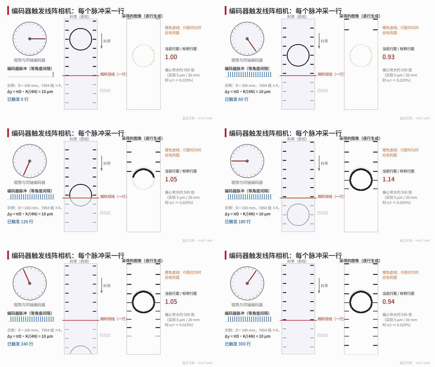
The line-spacing formula: how much web travel corresponds to each pulse
Let the encoder be coaxial with the roller, with line count N; after fourfold quadrature decoding there are 4N counts per revolution. The roller diameter is D and the web does not slip. The web displacement per count is πD/(4N). If the trigger module emits one line every K counts, the line spacing is
Δy = πD·K / (4N)
The object-side transverse pixel size is
Δx = p / m
where p is the sensor pixel size and m is the optical magnification. The condition for an undistorted image is Δy = Δx. In addition, the exposure should fill one line period so that the integrated width in the travel direction equals Δy; if the exposure is too short, unsampled gaps appear along that direction.
Example: D = 100 mm, roller circumference πD = 314.16 mm, required Δx = 10 μm, K = 1, then
N = πD / (4Δx) = 314.16 / (4 × 0.010) = 7853.98
Taking 7854 lines, the line spacing is 9.99998 μm, a deviation of only two parts per million. But 7854 is not a common line count. The table below lists approaches with readily available line counts (fourfold quadrature decoding, K = 1):
| Line count N | Counts per revolution | Object-side distance per count | Count frequency at 0.4 m/s | Approach |
|---|---|---|---|---|
| 7854 | 31 416 | 10.00 μm | 40.0 kHz | Direct match; a custom line count is required |
| 10 000 | 40 000 | 7.854 μm | 50.9 kHz | Adjust the lens so that Δx = 7.854 μm (m = 1.273), and limit the speed or use frequency division |
| 5000 | 20 000 | 15.71 μm | 25.5 kHz | Lens m = 0.637, object-side pixel 15.7 μm |
| 2500 | 10 000 | 31.42 μm | 12.7 kHz | Line spacing too coarse; a 10 μm pixel would undersample |
In practice it is more common to fix the roller diameter and the encoder first, and then trim Δx with the lens magnification, because magnification can be adjusted continuously whereas line count cannot. When the trigger module can combine multiplication and frequency division into a rational ratio, ratios such as π/4 can also be approximated, provided the residual is smaller than the uncertainty of the roller diameter itself.
Line rate, web speed and interface frequency
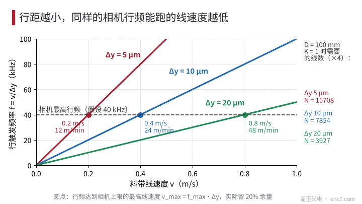
The camera has a maximum line rate f_max. The line rate is f = v / Δy, so the maximum web speed is
v_max = f_max · Δy
Assume a camera maximum line rate of 40 kHz: at Δy = 10 μm, v_max = 0.4 m/s (24 m/min); at Δy = 5 μm it is only 0.2 m/s; at Δy = 20 μm it can reach 0.8 m/s, see Figure 2. To run at 1 m/s on a production line with a 40 kHz camera, the line spacing cannot be smaller than 25 μm. In engineering practice a 20% margin is recommended, so that pulses do not exceed the frequency the camera can follow and lines are not dropped.
The frequency on the encoder side must be checked as well: at 0.4 m/s the roller speed is about 76.4 r/min, the A/B frequency of a 7854-line encoder is only 10 kHz, and 40 kHz after fourfold quadrature decoding, which is no strain at all for a differential interface. The real limit is almost always on the camera side. If the encoder count frequency is higher than the camera’s upper limit, frequency division K should be used to enlarge the line spacing until it matches the adjusted Δx, rather than letting the camera drop pulses.
Periodic line-spacing error caused by eccentricity
When the encoder disc has eccentricity e and the read radius is r, the measured angle exceeds the true angle by a once-per-revolution term:
θ_enc = θ + (e/r)·sin(θ + φ)
Triggering is issued at equal intervals of θ_enc, so the interval in true angle is 1/[1 + (e/r)·cos(θ + φ)], and the line spacing becomes
Δy(θ) ≈ Δy0 · [1 − (e/r)·cos(θ + φ)]
The accumulated line-position error is
δy(θ) = −R·(e/r)·sin(θ + φ)
where R is the roller radius and φ is the azimuth of the eccentricity. Note the two different magnitudes: the relative change of adjacent line spacings is only e/r; with e = 5 μm and r = 20 mm this is 0.025% (about 52″), only 2.5 nm on a 10 μm line spacing, and a circular pattern shows no visible distortion. The amplitude of the line-position error, however, is R·e/r, which reaches 12.5 μm at R = 50 mm, about 1.25 lines; two features half a revolution apart (157 mm) can differ by as much as 25 μm.
| Encoder eccentricity e / read radius r | e/r | First-order error | Position-error amplitude at R = 50 mm |
|---|---|---|---|
| 3 μm / 20 mm | 0.015% | 31″ | 7.5 μm |
| 5 μm / 20 mm | 0.025% | 52″ | 12.5 μm |
| 10 μm / 10 mm | 0.10% | 206″ | 50 μm |
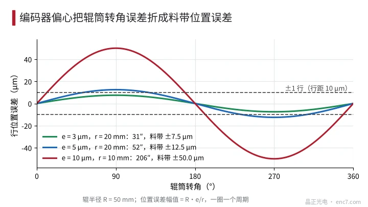
This error is proportional to the roller radius R, so the same encoder is worse off on a large roller than on a small measuring wheel. For inspection that is concerned only with the appearance of the pattern, it can be ignored; for inspection that must locate a defect to within 0.05 mm, it must be entered into the budget together with the roller’s radial runout (often larger: 20 μm of runout turns directly into about 20 μm of position error) and with slip.
Engineering points
- First write the equality Δy = πD·K/(4N) = Δx = p/m, then choose the line count; if the line count does not come out to a standard value, compensate with the lens magnification.
- The roller diameter itself has uncertainty: a diameter error of 0.1 mm is a scale error of 0.1%, and an image 100 mm long is in error by 0.1 mm. After the line is commissioned, the actual line spacing should be calibrated with a scale target.
- Check the maximum web speed with v_max = 0.8·f_max·Δy, and at the same time check whether the encoder count frequency exceeds the camera’s maximum line rate.
- Mount the encoder on a driven roller or on a measuring wheel that runs on the web, avoiding transmission error and slip through belts and couplings.
- The trigger module must include direction discrimination, so that a reverse jitter of the web does not emit a line twice.
- At a roller radius of 50 mm and a read radius of 20 mm, keeping encoder eccentricity within 5 μm keeps the position-error amplitude below 1.3 lines; tighter requirements call for diametrically opposite readheads.
In brief
The longitudinal resolution of a line-scan camera is determined entirely by encoder triggering. The core of the configuration is that Δy = πD·K/(4N) equals the object-side pixel p/m, while the line rate stays within the camera’s limit. The change in line spacing caused by eccentricity is minute, but it accumulates into a periodic position error of amplitude R·e/r; whether that matters depends on the positioning accuracy required of the inspection.
Translated from the ENC7 Chinese technical library (article 0771). Read the Chinese original. Need a disc built to your drawing? Request a quote or see our custom encoder discs.
© Langfang Jingzheng Optoelectronic Technology Co., Ltd. All rights reserved. This article was created with AI assistance.