Manufacturing
Exposure: Printing the Pattern onto the Encoder Disc

Exposure is the core step of photolithography: ultraviolet light passes through the photomask and “prints” the disc pattern into the photoresist. This article explains the difference between contact and proximity exposure, why the dose has to be just right, how gap and wavelength limit the finest printable line, and what alignment has to match.
In an old-style photo studio, prints were made by pressing the negative onto photographic paper and switching on a lamp briefly; the image on the negative was “printed” onto the paper. Exposure of an encoder disc works almost the same way: the negative becomes a photomask, the photographic paper becomes chrome-coated glass covered with photoresist, and the lamp becomes ultraviolet light. The difference is that the lines to be printed here may be only a few microns wide.
Exposure needs three things
- Photomask: the disc pattern made in chrome on clear glass – the “negative”. For 1:1 replicated patterns such as encoder discs, the mask is the same size as the disc.
- Ultraviolet light: commonly the UV lines of a mercury lamp, for example the 365 nm i-line; UV LEDs are also used. The light should be as collimated as possible with uniform irradiance.
- Photoresist: sensitive only to ultraviolet and short-wavelength light, which is why the lithography room is lit with yellow light.
With the commonly used positive resist, the exposed areas become soluble in the developer. Where the opaque chrome on the mask blocks the light, the resist remains, and the chrome beneath it is kept as the lines. So with positive resist, black and white on the mask match black and white on the disc.
Contact and proximity
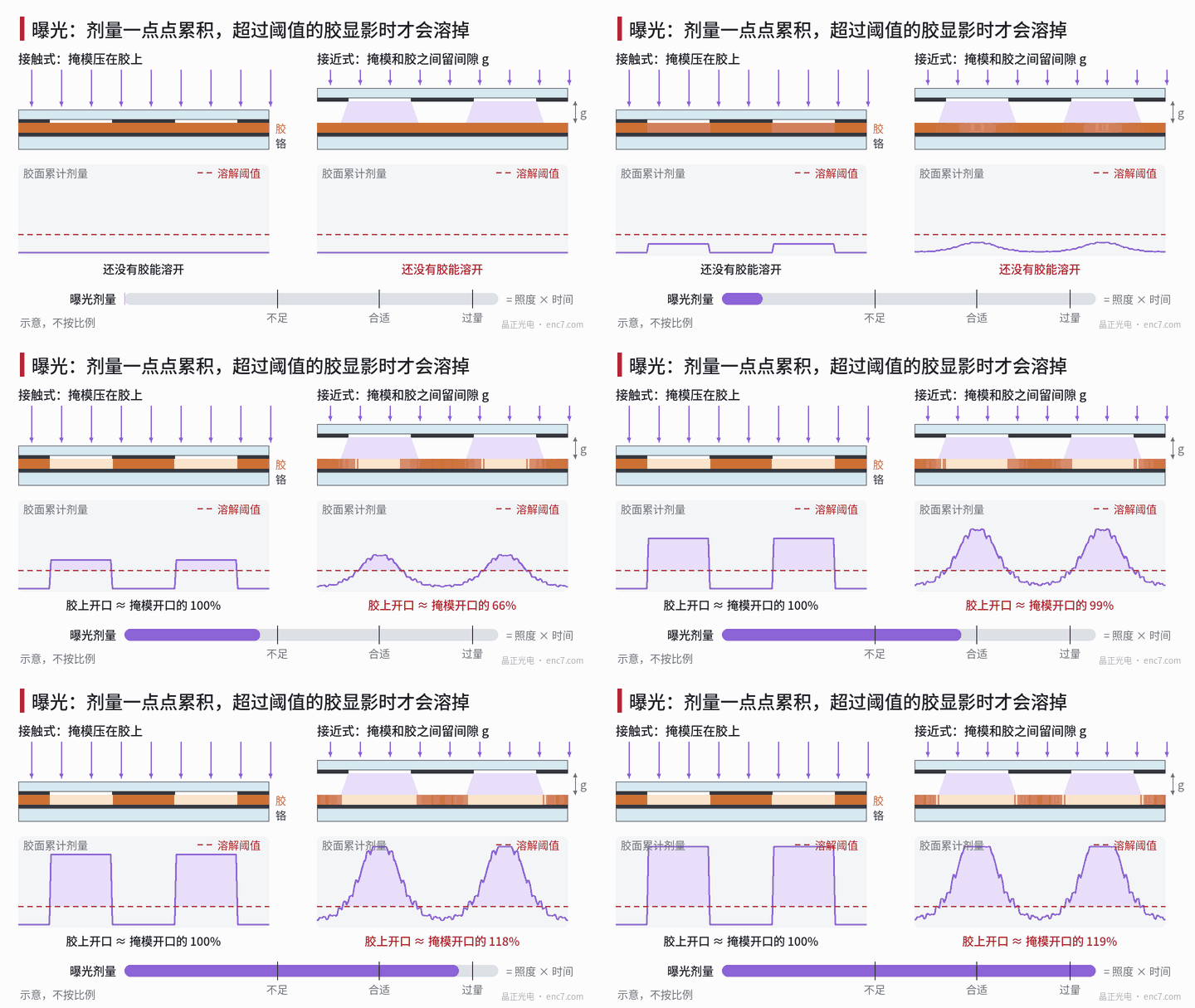
See Figure 1. Contact exposure presses the mask directly onto the resist surface; the light goes straight down through the openings with hardly any spreading, and edges are sharp. The price is that the mask repeatedly touches the resist and easily wears, picks up resist or collects particles – a single particle can print a defect on every subsequent plate.
Proximity exposure leaves a small gap g between mask and resist; the mask does not touch the resist, so it lasts longer and defects are fewer. But light diffracts after passing through the opening, edges blur, and part of the light “leaks” under the chrome lines – the dose curve on the right of Figure 1 is no longer a steep rectangle.
Exposure dose: it has to be just right
Exposure dose = irradiance × time. Only where the dose accumulated at a point of the resist surface exceeds a threshold will the resist at that point dissolve in development.
- Underexposure: the opening does not fully clear, or a thin layer of residual resist remains at the bottom; after etching residual chrome is left and the clear slit becomes narrower.
- Overexposure: light leaking past the edges also accumulates above the threshold, the opening widens and the chrome line becomes thinner.
The right side of Figure 1 illustrates this with a simplified diffraction model: for the same mask opening, the opening in the resist is only about 79% of the mask opening when underexposed, about the same width at the correct dose, and about 119% when overexposed. In contact exposure the edges are steep, so the same dose change causes a much smaller line-width change.
Lamp irradiance falls with hours of use, so it should be measured regularly with an irradiance meter and the time adjusted. If irradiance drops by 10%, exposure time must be extended by about 11% (1 ÷ 0.9 ≈ 1.11) to keep the dose unchanged.
What limits resolution
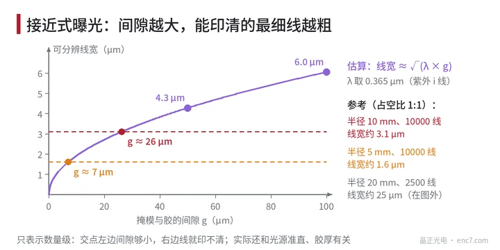
The finest line that proximity exposure can print cleanly can be roughly estimated as √(λ × g). With λ = 0.365 μm:
| Gap g | Estimated resolvable line width |
|---|---|
| 10 μm | about 1.9 μm |
| 50 μm | about 4.3 μm |
| 100 μm | about 6.0 μm |
Compare with discs at a 1:1 duty cycle: at radius 20 mm with 2500 lines the line width is about 25 μm, so the gap can be much looser; at radius 5 mm with 10000 lines the line width is only about 1.6 μm, the gap must shrink to a few microns, and essentially only contact exposure will do (see Figure 2).
In addition, insufficiently collimated light also blurs edges: a ray tilted by 1° drifts sideways by about 0.5 μm after crossing a 30 μm gap. Although contact exposure has no gap, it is still affected by resist thickness and by whether mask and substrate are in even contact.
Alignment: where the pattern goes
A disc pattern usually has only one layer, so alignment mainly ensures that the pattern lands in the correct place on the substrate and, together with the centring ring and marks on the mask, provides the datum for subsequent cutting and assembly. Double-sided or multilayer patterns require aligning mask marks to substrate marks under a microscope. Mask and substrate must also be parallel, with the gap the same everywhere; otherwise line width will vary within a single plate.
Summary
Exposure copies the pattern on the mask into the resist. Contact exposure is sharp but wears the mask; proximity protects the mask but blurs. Dose determines how wide the openings are, while gap and wavelength determine how fine a line can be printed. The finer the lines on a disc, the more demanding the exposure.
Translated from the ENC7 Chinese technical library (article 0024). Read the Chinese original. Need a disc built to your drawing? Request a quote or see our custom encoder discs.
© Langfang Jingzheng Optoelectronic Technology Co., Ltd. All rights reserved. This article was created with AI assistance.