Competing technologies and trends
Fibre-transmitted encoders: moving the electronics out of harsh environments
With the light source and the detectors placed remotely and the optical signals carried by fibre, the readhead is left with only the encoder disc and the optics. This article gives the optical power budget of that arrangement (about 4 μW at the detector from a 5 mW source), estimates the signal-to-noise ratio, and quantifies three main limitations: unequal loss among channels, channel count, and transmission delay.
In large generators, high-voltage switchgear, MRI equipment, hazardous areas and high-temperature equipment, the most vulnerable part of an encoder is often not the disc but the LED, the photodiodes and the chip in the readhead: they are sensitive to strong electromagnetic fields, high temperature and radiation, and may themselves become an ignition source. One idea is to move all of these electronic devices tens of metres away into a safe area, send the light to the disc through fibre, and send the modulated light back. What is the cost of doing so? This article starts from the optical power budget.
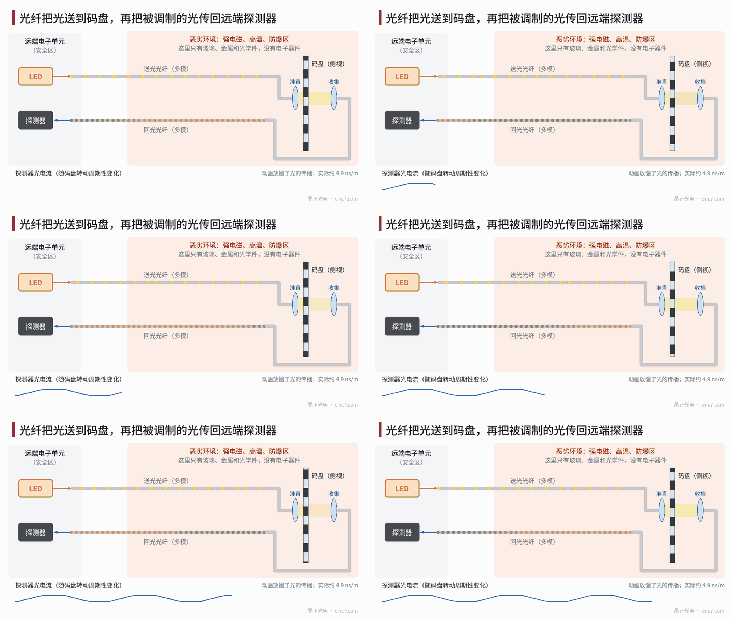
Arrangement: a passive readhead plus a remote optoelectronic unit
The readhead of a fibre-optic encoder consists of the end face of the send fibre, a collimating lens, the encoder disc, an index-grating window and a collecting lens, with no active devices at all. The remote unit contains the light source, the detectors and the interpolation circuitry. To obtain the two sine/cosine signals, an index-grating window can be placed in front of each of two return fibres, offset from each other by 1/4 period; the disc may be a transmissive glass encoder disc or a reflective metal encoder disc.
Optical power budget
The first hurdle of a fibre scheme is that there is too little light. The efficiency with which a Lambertian LED couples into a multimode fibre, when the emitting area is larger than the core, is about
η ≈ NA² · (a_core / a_src)²
where NA is the numerical aperture of the fibre and a_core, a_src are the radii of the core and of the emitting area. With NA = 0.22, a 200 μm core and a 300 μm emitting area, η ≈ 2.2%, or −16.7 dB; when the emitting area is smaller than the core, η is approximately equal to NA², or 4.8%.
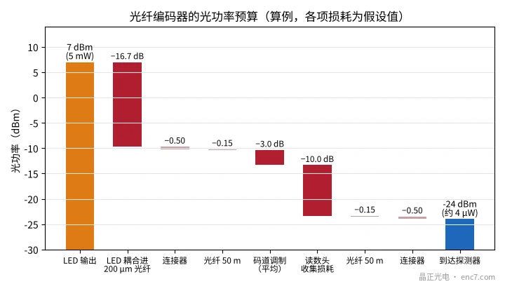
Worked example (the individual losses are assumed values; see Figure 2):
| Stage | Loss | Cumulative optical power |
|---|---|---|
| LED output 5 mW | — | +7.0 dBm |
| Coupling into the fibre | 16.7 dB | −9.7 dBm |
| Connectors + 50 m of fibre | 0.65 dB | −10.3 dBm |
| Track modulation (mean transmittance about 50%) | 3 dB | −13.3 dBm |
| Readhead collection into the return fibre | 10 dB | −23.3 dBm |
| 50 m of fibre + connectors | 0.65 dB | about −24 dBm (about 4 μW) |
At a responsivity of 0.5 A/W, the photocurrent is about 2 μA. Within a 1 MHz bandwidth the shot noise is √(2qIB) ≈ 0.8 nA, and the signal-to-noise ratio is about 2500 (68 dB); the thermal-noise current of a 1 MΩ feedback resistor is about 0.13 nA and has a smaller effect. With σ_φ ≈ 1/SNR, the electrical-angle noise is about 4×10⁻⁴ rad, which is enough for incremental counting and for interpolation at a moderate factor.
Choice of light source: a laser or a VCSEL couples much more efficiently, but coherent light forms speckle in a multimode fibre. With a 200 μm core, NA 0.22 and a wavelength of 850 nm, the normalized frequency is V = 2πa·NA/λ ≈ 163, and the number of guided modes is about V²/2 ≈ 1.3×10⁴. As soon as the fibre moves, the speckle pattern changes, and after spatial filtering by disc slits and an index grating this appears as random fluctuations of intensity — modal noise. A low-coherence LED avoids this problem, so LED sources are commonly used in multimode-fibre schemes.
First limitation: unequal loss among channels
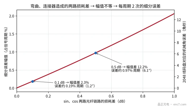
The sine and cosine signals travel in different fibres, so bending, repeated connector mating and fibre ageing can make the two paths differ in loss. Photocurrent is proportional to optical power, and a loss difference Δ (dB) corresponds to an amplitude ratio 10^(Δ/10). From the usual interpolation-error relation, a relative amplitude difference δ produces an electrical-angle error of about δ/2 rad, occurring 2 times per period (see Figure 3):
| Two-path loss difference | Amplitude difference | Error (fraction of a period) | Equivalent on a 2048-line disc |
|---|---|---|---|
| 0.1 dB | 2.3% | 0.19% | about 1.2″ |
| 0.5 dB | 12.2% | 0.97% | about 6.1″ |
The difficulty is that this error changes as the cable moves, so a factory calibration can only take care of the static part. Practical remedies include: fitting the Lissajous figure on-line during motion and correcting the amplitudes in real time; adding a reference channel for normalization; and using wavelength-division multiplexing so that several signals share one fibre, making bending loss essentially common-mode (bending loss is wavelength-dependent, so the cancellation is only partial).
Second limitation: channel count and absolute encoding
An incremental encoder needs only two or three signal channels; an absolute encoder is more awkward: 16-bit Gray code requires 16 tracks, each needing a return-light channel, and the cable becomes both thick and expensive. Two lines of research exist: one is spectral encoding, using a broadband source, with a dispersive element in the readhead assigning different wavelengths to different tracks and a spectrometer at the remote end doing the decoding; the other is time-division multiplexing, distinguishing channels by delay lines of different fibre lengths — the delay in fibre is about 4.9 ns/m, so resolving 1 ns requires a length difference of about 0.2 m. Both add complexity at the remote equipment.
Third limitation: delay, temperature and environment
- Delay: 100 m of return fibre has a delay of about 0.49 μs. At 6000 r/min this is equivalent to an angular lag of about 63″, which needs to be compensated in high-speed synchronized control.
- Temperature: the readhead can be made entirely of glass, metal and optics, but the fibre coating has an upper temperature limit — a typical acrylate coating is about 85 °C, a polyimide coating can reach around 300 °C; adhesives, bearings and lubricants often reach their limit first. Differential thermal expansion of the materials also changes the optical alignment and causes amplitude variation.
- Radiation: the electronics have been moved out of the radiation area, but fibre darkens under irradiation, so radiation-hard fibre must be selected.
- Explosion protection: the readhead has no electrical power, but the optical power itself may still be an ignition source and must be assessed to IEC 60079-28.
| Application | Main problem | Value of a fibre scheme |
|---|---|---|
| Large generators, high-voltage equipment | Strong electromagnetic fields, high potential difference | Dielectric transmission, inherent electrical isolation |
| Hazardous area | Electrical sparks | Readhead has no electrical power |
| High-temperature equipment | Temperature rating of semiconductor devices | Readhead contains only optics |
| Strong magnetic-field equipment | Magnetic materials and electronic interference | Can be built entirely of non-magnetic materials |
Engineering points
- Do the optical power budget first: coupling and collection often account for more than ten decibels each; from a 5 mW source only microwatts remain at the detector, and the signal-to-noise ratio must be worked out from that.
- Pair a multimode fibre with an LED: avoid the modal noise that a coherent source produces in a multimode fibre.
- Treat the two-path loss difference as an error source: a 0.5 dB difference produces about 1% of a period of interpolation error, so on-line amplitude correction or a common-mode design is needed.
- The optical cable must be fixed: reduce changes of bend during motion, and specify a minimum bend radius.
- Compensate the delay on a long cable: about 4.9 ns/m, which at high speed converts into an angular lag.
- Check the temperature ceiling by material: coating, adhesive, bearings and lubricant, item by item.
Summary
Fibre transmission moves the encoder electronics out of the harsh environment and in return provides electrical isolation, electromagnetic immunity and temperature capability. The cost is microwatt-level optical power, interpolation error from unequal loss among channels, the channel-count problem of absolute encoding, and transmission delay. It is suited to places that electronics cannot enter; the disc and the optics in the readhead still set the upper limit on signal quality.
Translated from the ENC7 Chinese technical library (article 0189). Read the Chinese original. Need a disc built to your drawing? Request a quote or see our custom encoder discs.
© Langfang Jingzheng Optoelectronic Technology Co., Ltd. All rights reserved. This article was created with AI assistance.