Glass & substrate science
Float, Overflow Downdraw and Ground-Polished Substrates: Roughness, Flatness and Thickness Deviation

Float glass is fire-polished but wavy; overflow downdraw forms without contact on either face; grinding and polishing give controllable flatness. This article compares the three substrate routes on flatness, waviness and roughness scales, estimates wedge angle from thickness deviation and the gap needed for proximity exposure, and outlines encoder-disc substrate selection.
A transparent glass sheet nominally 1 mm thick may come from float, overflow downdraw or grinding-and-polishing. Their surface states differ: some are nanometre-smooth yet slightly bowed over the sheet, others are flat but need an extra process step, and prices differ. The key to selection is the scale of the undulation: saying “how flat is the surface” always means “over what lateral window”. This article places the three substrate types on a common assumed surface-spectrum model and then compares them with encoder-disc and proximity-exposure requirements.
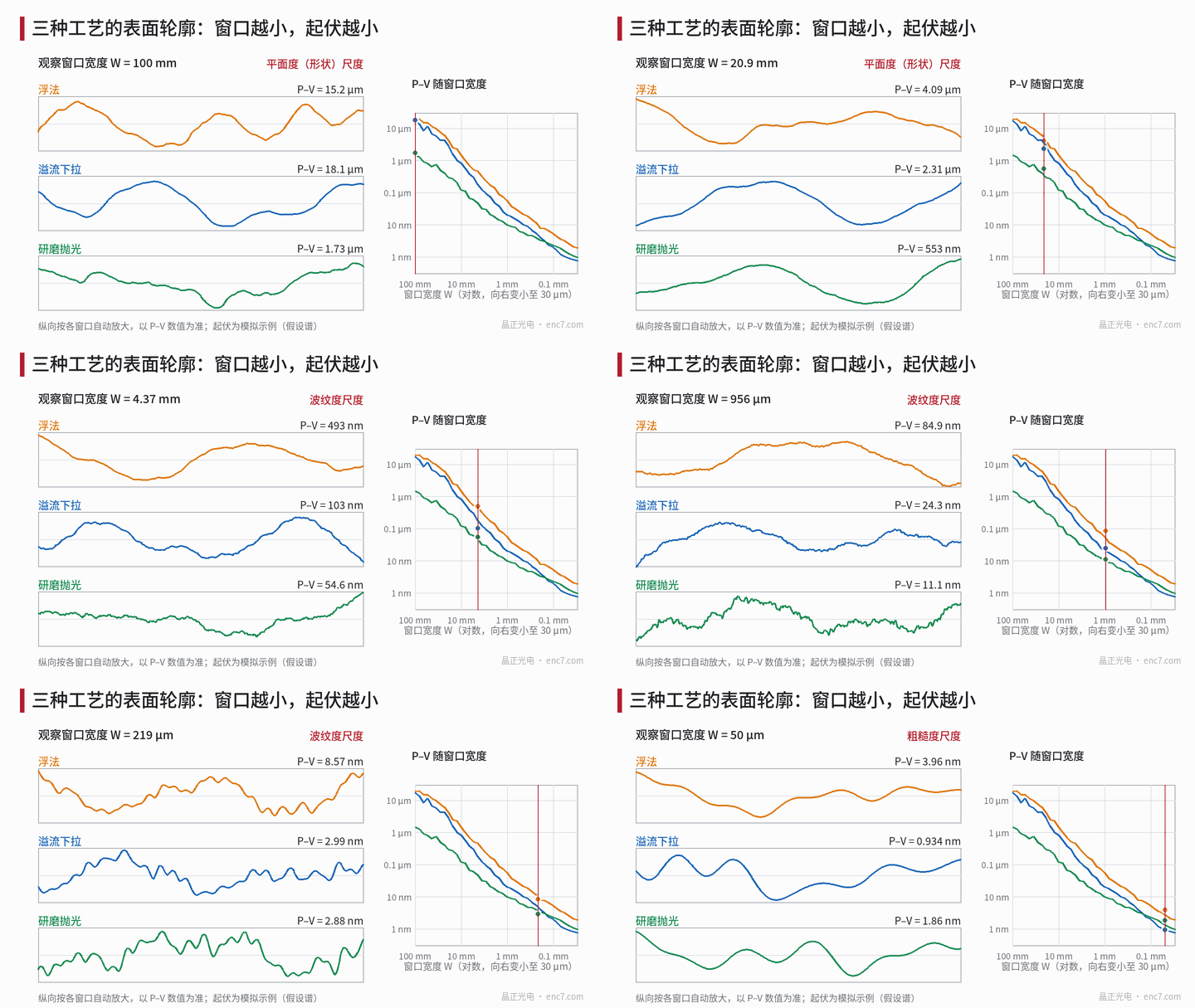
Where the three surfaces come from
Float glass is spread into a ribbon on a molten tin bath; the upper face is formed by surface tension and fire polishing and is nanometre-smooth, but long-wave undulations run along the draw direction; the tin-contact face is covered in the tin-side article of this library. Overflow downdraw lets two glass streams flow down the sides of an overflow trough and fuse at the root into a sheet whose outer faces never touch a forming member; thinner sheets often use this route. Grinding and polishing flatten both faces of an existing glass plate and then polish them, removing the near-surface subsurface damage (see the grinding article in this library); the shape is set by the grinding-plate face and the polishing process.
Looking by scale: flatness, waviness, roughness
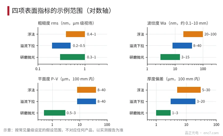
By spatial wavelength, undulations are often split into three bands: above about 10 mm as flatness (form), 0.1–10 mm as waviness, and shorter as roughness. Example (assumed): float form rms 10 μm, waviness 40 nm, roughness 0.7 nm; overflow downdraw 8, 15 nm, 0.3 nm (thin sheet free state); ground-polished 0.8 μm, 5 nm, 0.4 nm. From this spectrum the P–V in each window follows (Figure 1, right):
| Observation window | Float | Overflow downdraw | Ground-polished |
|---|---|---|---|
| 100 mm | about 19 μm | about 18 μm | about 1.5 μm |
| 2 mm | about 0.15 μm | about 0.055 μm | about 0.019 μm |
| 50 μm | about 2.9 nm | about 1.0 nm | about 1.4 nm |
Three readings. First, P–V on the same sheet falls by several orders of magnitude as the window shrinks, so “P–V = …” must always state the window and the filtering. Second, on large scales ground-polished is the flattest; on small-scale roughness overflow downdraw is lowest because there is no mechanical working; all three nanometre-class roughnesses give negligible scatter loss at 850 nm infrared (see the roughness-and-scatter article in this library). Third, in the example float waviness is higher than overflow downdraw, but the difference varies by sheet batch; the ranges in Figure 2 are order-of-magnitude only.
The effect of waviness on transmission can be estimated: for an amplitude of 0.05 μm and wavelength 5 mm the maximum slope is 2π·a/λ ≈ 63 μrad ≈ 13″; single-face refraction deflects by about (n−1) times, i.e. of order 30 μrad, giving only 0.03 μm of displacement over a 1 mm reading gap – negligible.
Thickness deviation and wedge angle
Thickness deviation turns the sheet into a wedge: a 20 μm difference over 100 mm is a wedge angle of 0.2 mrad (41″); the transmitted ray deflects by about (n−1) times, i.e. 0.1 mrad, only about 0.1 μm over a 1 mm reading gap. For incremental encoder discs the effect is small, but for a whole sheet used as a diffraction grating, for long optical paths or for stacked plates it must be checked separately; ground-polished plates usually have deviations of only 1–3 μm order.
Requirements for encoder discs and proximity exposure
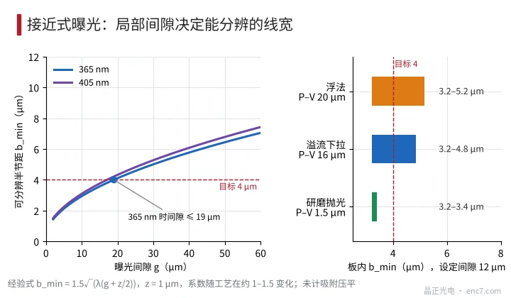
In proximity exposure a gap g is left between mask and substrate; diffraction widens the resolvable linewidth as the gap grows. A common empirical form (factor 1–1.5 depending on process) is:
b_min ≈ 1.5·√(λ·(g + z/2))
where b is the linewidth of equal-line equal-space patterns (half-pitch) and z the resist thickness, taken as 1 μm. At 365 nm, g = 10, 20, 30, 50 μm give b_min about 2.9, 4.1, 5.0, 6.4 μm. For a target pitch of 8 μm (half-pitch 4 μm) the gap must not exceed about 19 μm, and this must hold over the whole sheet.
With a set gap of 12 μm and substrate form P–V of 20 μm (float example), the local gap runs from 12 to 32 μm and b_min rises from about 3.2 μm to 5.2 μm, missing the 4 μm target; a ground-polished plate with P–V 1.5 μm stays at 3.2–3.4 μm (Figure 3, ignoring vacuum chuck flattening). A thin sheet pulled flat on a vacuum chuck improves, but flattening needs enough flexibility and a flat chuck.
Selection thinking
| Encoder-disc type (example thresholds) | Preferred choice |
|---|---|
| Pitch not below several tens of μm; contact or projection exposure; reading gap above 0.3 mm | Float is enough; watch tin side and annealing |
| Pitch 10–20 μm; proximity exposure; gap 10–30 μm | Overflow downdraw or ground-polished, depending on P–V and chuck |
| Pitch below about 8 μm; diffractive or reflective readout | Ground-polished, with μm-class flatness and thickness-deviation specs |
Engineering notes
- Flatness, waviness and roughness in a specification must carry window width and filtering method, otherwise they cannot be compared.
- Roughness (nm class) is seldom the issue for glass substrates; flatness and thickness deviation are.
- For proximity exposure first back-calculate the allowed gap from the target linewidth, then require in-sheet form P–V to be only a fraction of that allowed gap.
- Free-state shape of thin sheets depends on residual stress and self-weight; incoming inspection should measure under a fixed support.
- For ground-polished plates check that subsurface damage has been removed; edge chamfer and cleanliness also belong in the specification.
- Before selection, check the ranges in this article against measured reports; batch-to-batch and supplier differences can reach several times.
Summary
Float, overflow-downdraw and ground-polished substrates all have nm-class roughness; what really separates them is flatness and thickness deviation on the 100 mm scale: in the example the ground-polished P–V is about 1.5 μm, while free float and overflow sheets are about 20 μm. Proximity-exposure gap requirements turn that difference into a linewidth difference, so choose the substrate by target pitch rather than saying “it must be flat” in the abstract.
Translated from the ENC7 Chinese technical library (article 0568). Read the Chinese original. Need a disc built to your drawing? Request a quote or see our custom encoder discs.
© Langfang Jingzheng Optoelectronic Technology Co., Ltd. All rights reserved. This article was created with AI assistance.