Encoder-disc terminology
Grating Equation: Diffraction Angle and Order Separation

The grating equation sets the direction of every diffracted order. This article gives diffraction angles for 20, 8 and 4 μm pitch at λ = 0.88 μm, derives the in-gap lateral separation g·tanθ_m and its links to the near-field condition, illumination margin and detector-zone crosstalk, and explains why trapped orders and spectral broadening make stray light harder to control as pitch shrinks.
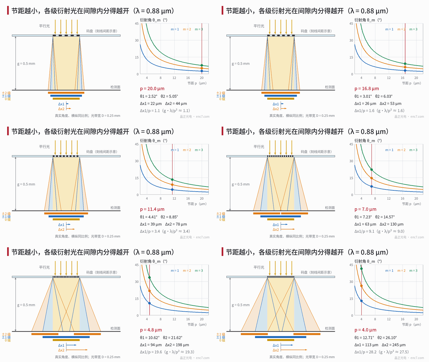
With the same readhead layout, shrinking encoder-disc pitch from 20 μm to 4 μm often does not make the signal smaller in proportion; it changes how it fails: imaging fringes disappear, detector zones crosstalk, and stray light can be measured on a track millimetres away from the read point. All of these start from the grating equation. An introductory note said “finer lines make light bend more”; this article works out by how many degrees and where that light lands in the gap.
Definition: grating equation and diffraction orders
Lines of period p repeat along the measuring direction, so the transmitted (or reflected) light can only be a set of plane waves in discrete directions—the diffraction orders. Phase matching gives the grating equation:
sinθ_m = sinθ_i + m·λ/p
where θ_i is the incidence angle, θ_m the diffraction angle of order m (m = 0, ±1, ±2…), both measured from the normal in the plane containing the grating vector; λ is the vacuum wavelength and p the pitch. Four points matter in use:
- A reflective disc uses the same formula, with θ_m measured on the incidence side;
- For radial lines the grating vector is perpendicular to the lines and tangential, so the orders fan out along the track direction, not toward neighbouring radial tracks;
- Inside glass write n·sinθ_m,g = sinθ_i + m·λ/p; a parallel glass plate does not change the angle after exit into air;
- Only orders with |sinθ_i + m·λ/p| ≤ 1 can enter air; at normal incidence the highest order is the integer part of p/λ.
Numerical example: three pitches
At λ = 0.88 μm and normal incidence, Δx_m = g·tanθ_m is the lateral separation of order m relative to order 0, and g is the distance from disc to detection plane (index grating or photodiode):
| Pitch p | θ_1 | θ_2 | θ_3 | Propagating orders | g = 0.1 mm: Δx_1 / Δx_2 | g = 0.5 mm: Δx_1 / Δx_2 |
|---|---|---|---|---|---|---|
| 20 μm | 2.52° | 5.05° | 7.59° | to ±22 | 4.4 / 8.8 μm | 22 / 44 μm |
| 8 μm | 6.32° | 12.71° | 19.27° | to ±9 | 11 / 23 μm | 55 / 113 μm |
| 4 μm | 12.71° | 26.10° | 41.30° | to ±4 | 23 / 49 μm | 113 / 245 μm |
At small angles θ ≈ λ/p and angle is inversely proportional to pitch; when pitch is only a few wavelengths θ grows faster than inverse, and at 4 μm pitch order 3 already reaches 41°, tanθ_3 ≈ 0.88 (see Figure 2).
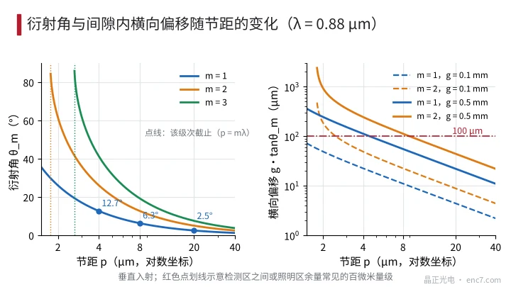
Lateral separation and reading methods
Near-field condition. The ratio of order-1 offset relative to order 0 to the pitch is Δx_1/p ≈ g·λ/p². Imaging readout requires g much smaller than p²/λ—equivalently, the ±1-order offset relative to order 0 much smaller than one pitch—so the three can still stack into a sharp shadow; at the Talbot distance g = 2p²/λ the offset is exactly 2 pitches (paraxial approximation). At 20 μm and g = 0.1 mm the ratio is 0.22 and the image is sharp; at 8 μm and g = 0.5 mm it is already 6.9, so the design must use Talbot self-imaging or an interferential scheme.
Illumination margin. The illuminated zone must extend beyond the detection window by g·tanθ_m on each side along the measuring direction (m the highest order that contributes to the signal); otherwise the window ends miss orders and amplitude and harmonic content there differ from the centre. At g = 0.2 mm, counting to order 3, a 20 μm pitch needs about 27 μm and a 4 μm pitch about 176 μm.
Detector-zone crosstalk. When zones A, B and so on sit side by side along the measuring direction, light diffracted from one zone of the index grating shifts by g′·tanθ_m before it reaches the photodiode (g′ the distance from index grating to diode). If the shift exceeds the isolation band between zones, light of a different phase from a neighbour mixes in, seen as amplitude drop and A/B phase error. At 4 μm pitch even g′ = 0.1 mm gives about 49 μm shift for order 2.
Interferential readout is the opposite: it needs ±1 separated from 0 and from ±2. For beam width D = 0.5 mm the distance for full separation of ±1 from 0 is about D/tanθ_1: 11.4 mm at 20 μm pitch, only 2.2 mm at 4 μm. That is one geometric reason interferential readout suits fine pitch; at coarser pitch, orders can be separated by spatial filtering with a lens in the focal plane.
Why stray orders are harder to control as pitch shrinks
Large-angle orders travel farther. For a fixed readhead size, lateral shift grows as 1/p, and at large angles tanθ accelerates further. At 4 μm pitch and g = 0.5 mm, order 3 shifts about 0.44 mm—enough to hit a readhead sidewall, another detector zone or the disc edge and reflect back as stray light.
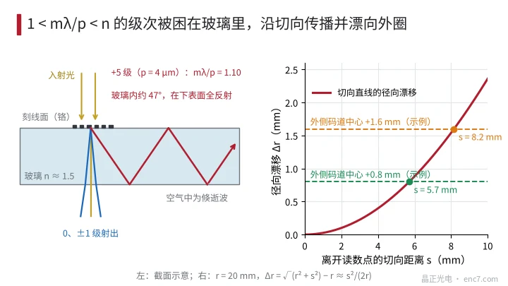
Orders trapped in the glass. Orders with 1 < |m·λ/p| < n are evanescent in air but can propagate in glass; at a glass–air interface they total-reflect and stay trapped inside the disc. At 4 μm pitch these are orders 5 and 6: order 5 is about 47° in glass, and in a 1.5 mm thick disc each round trip advances about 3.2 mm tangentially. Estimating with a scalar thin grating, sharp edges and 50% duty cycle, trapped power is about 0.16%, 0.29% and 0.81% at 20, 8 and 4 μm pitch—about 0.8%, 1.4% and 4.0% of the total ±1-order power—and rises roughly as λ/(π²·p)·(1 − 1/n) as pitch shrinks (when pitch is only a few wavelengths the scalar model is only an order-of-magnitude guide). The reason is that the spatial frequencies of these orders always lie between 1/λ and n/λ, independent of pitch, while the number of line edges per millimetre scales as 1/p. Trapped light meeting the patterned face is re-diffracted out; light that travels in a straight tangential line leaves the read point by s and the radius becomes √(r² + s²)—at r = 20 mm, after 5.7 mm it has drifted outward by 0.8 mm (see Figure 3) and may fall into an outer-track detection window.
Spectral width and temperature drift. dθ_m/dλ = m/(p·cosθ_m). Assuming an LED spectral width of 40 nm, the angular width of order 1 is about 2.0 mrad at 20 μm pitch and about 10.3 mrad at 4 μm; at g = 0.5 mm the lateral blur is about 1.0 μm and 5.1 μm—0.05 and 1.3 pitches respectively—so in the latter case monochromatic self-imaging detail is already washed out. At a wavelength temperature drift of order 0.25 nm/K, a 60 K rise shifts the order-1 angle at 4 μm pitch by about 3.8 mrad.
Engineering points
- First list every propagating order and its angle with sinθ_m = sinθ_i + m·λ/p, taking λ at the LED peak and extending for spectral width and temperature drift, then choose the reading method.
- Use g·λ/p² to judge whether imaging is feasible: much less than 1 means a sharp shadow; near or above 1 means design for Talbot imaging or interferential readout.
- Extend the illuminated zone at least g·tanθ_m beyond the detection window on each side (m the highest contributing order) so the window ends do not miss orders.
- Isolation bands between detector zones should exceed g′·tanθ_2; at fine pitch put the index grating directly on the detector surface so g′ approaches zero.
- When pitch is only a few wavelengths, account for orders trapped in the glass: apply absorbing treatment at the disc rim, between tracks and on readhead walls, and measure stray light away from the read point.
- Oblique illumination translates the whole order fan by about g·tanθ_i; positive and negative orders are no longer symmetric, so detector positions must be computed with the general formula.
Summary
The grating equation gives direction; multiply by the gap and you have the landing point. Shrinking pitch from 20 μm to 4 μm raises the order-1 diffraction angle from 2.5° to 12.7°, and lateral shift, spectral blur and trapped light all grow as 1/p or faster. Imaging readout relies on overlapping orders, interferential readout on separating them; the boundary between the two and the path of stray light can both be calculated from this one equation first.
Translated from the ENC7 Chinese technical library (article 0261). Read the Chinese original. Need a disc built to your drawing? Request a quote or see our custom encoder discs.
© Langfang Jingzheng Optoelectronic Technology Co., Ltd. All rights reserved. This article was created with AI assistance.