Introduction to encoder principles
Gray Code: Why Absolute Discs Do Not Use Ordinary Binary

An absolute disc must give every position a code, and the most direct idea is to use binary. But two adjacent binary numbers may differ in several bits at once, so a slight misalignment of the readhead can produce a wildly wrong value. In Gray code only one bit changes between adjacent positions, which avoids the problem at the root. This article explains the principle, the conversion, and how the tracks are drawn.
An absolute disc must give a code to every position around one revolution. The most direct method is to number the positions in order and write the numbers in binary: step 0 is 000, step 1 is 001, …, step 7 is 111. Each bit corresponds to one track on the disc; the readhead simply reads the light and dark of every track at once along a radius.
The reasoning is sound, but almost no real absolute disc is drawn this way: Gray code is used instead. The reason is hidden in the instant when the code changes from one step to the next.

The problem with binary: several bits change at once
Look at the change from step 3 to step 4: binary goes from 011 to 100, and all three bits flip at once.
In the ideal case the three bits would change at the same instant. In reality the edges of the tracks cannot be aligned to a hair, and the positions of the reading points on the readhead, the size of the light spots, and the comparison thresholds and delays of the circuit all differ slightly. If one bit changes a little earlier than the others, a transitional reading appears in between.
In Figure 1 the most-significant reading point is slightly ahead, so the sequence from 3 to 4 is 011 → 111 → 101 → 100, that is 3 → 7 → 5 → 4. A 3-bit disc has only 8 steps, and 7 and 3 are half a revolution apart. In one full revolution the binary disc is misread 6 times.
The more bits there are, the more serious the problem. On a 12-bit disc, going from 2047 to 2048, binary changes from 0111 1111 1111 to 1000 0000 0000 — all 12 bits flip, and the transitional value can be any number between 0 and 4095.
Gray code: only one bit changes between neighbours
The rule of Gray code is that two adjacent numbers differ in only one bit; see the table below.
| Position | Binary | Gray code |
|---|---|---|
| 0 | 000 | 000 |
| 1 | 001 | 001 |
| 2 | 010 | 011 |
| 3 | 011 | 010 |
| 4 | 100 | 110 |
| 5 | 101 | 111 |
| 6 | 110 | 101 |
| 7 | 111 | 100 |
From 7 back to 0, only one bit changes as well, 100 → 000, so the code joins end to end and suits a disc that turns revolution after revolution.
With only one bit changing there is no “transitional reading”: the readhead sees either the old value or the new one, at most one step out, and never jumps to a wildly wrong position. The Gray-code disc on the right of Figure 1, under the same misalignment, reads a steady 0 → 1 → 2 … → 7 → 0.
How to convert between binary and Gray code
The conversion uses only XOR (exclusive or: two bits the same give 0, different bits give 1); see Figure 2:
- Binary → Gray code: copy the most significant bit; each remaining bit is the XOR of that bit and the bit to its left. In a formula, G = B XOR (B » 1). For example, 1011 → 1110.
- Gray code → binary: copy the most significant bit; then, from high to low, each bit is the XOR of that Gray-code bit and the binary bit just obtained to its left. For example, 1110 → 1011.
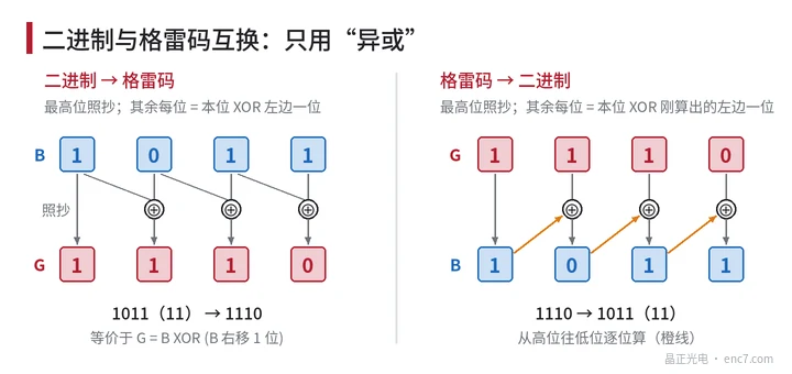
This conversion is usually done by the encoder’s internal circuit or by the controller; what the user reads is generally already a converted position value.
How the tracks are drawn on the disc
n-bit Gray code corresponds to n concentric tracks. The most significant bit changes least often and is usually placed on the inner ring; the least significant bit changes most often and is placed on the outer ring, where the circumference is larger.
Gray code has a further feature that helps manufacture: on the least-significant track, each opaque segment occupies 2 steps, whereas in binary the least-significant segments occupy only 1 step each. For the same number of bits, the line width of the finest Gray-code track is twice that of binary, and there are only half as many track edges, which is more forgiving for both photolithography and reading.
Absolute encoders with a very high bit count do not usually rely on ring after ring of Gray-code tracks alone; they use a few tracks to establish a coarse position and then interpolation signals to establish the fine position.
In brief
On a binary disc several bits may change at once at a step boundary, so a slight misalignment of the readhead can produce a wildly wrong value. In Gray code only one bit changes between adjacent positions, so the reading is at most one step out; the wrap-around also changes only one bit, which suits an encoder disc. The two codes can be converted with XOR, and the finest Gray-code track is twice as wide as the binary one, which is also kinder to manufacture.
Translated from the ENC7 Chinese technical library (article 0008). Read the Chinese original. Need a disc built to your drawing? Request a quote or see our custom encoder discs.
© Langfang Jingzheng Optoelectronic Technology Co., Ltd. All rights reserved. This article was created with AI assistance.