Encoder-disc terminology
Harmonic Distortion (THD): Harmonic Content of Encoder Sine Signals and How to Measure It
THD only gives the total harmonic content. This article derives its relation to interpolation error: the peak upper bound is about Σ|a_n|/a_1, about 2·THD when a second harmonic is present, and the lower bound can approach zero; a worked example shows how constant-speed sampling FFT under speed ripple reads 1.77% as 1.10%, why angle-synchronous resampling is needed for an accurate measurement, and how to write the specification.
Two readhead data sheets both write “THD ≤ 2%”, yet on the same disc the interpolation errors differ by a factor of two or three; the same readhead, re-tested on the bench at a different speed, shows THD changing from 1.8% to 1.1%. The first problem is in the THD figure of merit itself; the second is in the measurement method. This article first derives the relation between THD and interpolation error, then explains how to measure each harmonic accurately.
Definition: two denominators and the harmonics that matter for encoders
Expand the waveform of one signal period as a Fourier series with a_n the amplitude of the nth harmonic. The common definition is
THD = √(a_2² + a_3² + a_5² + …) / a_1
with the fundamental as denominator. Another definition uses the RMS of all AC components as denominator, THD_R = THD/√(1 + THD²); when distortion is small the two are almost identical: a triangular wave has THD = 12.1% and THD_R ≈ 12.0%; a square wave has THD = 48.3% and the difference becomes noticeable. Adding the noise inside the measurement bandwidth yields THD+N, whose value depends on bandwidth. In dB, 1.77% is about −35 dB. DC offset is not counted in THD.
For encoder signals three terms matter most: the second harmonic comes from asymmetry of a single-ended signal or from duty-cycle departure, and is largely cancelled by differential subtraction when A+ and A− are complementary; the third and fifth harmonics come from a waveform that leans triangular or trapezoidal and depend on duty cycle, detection-window shape and gap.
THD and interpolation error: only an upper bound, not a fixed value
Following the mapping in the interpolation-error harmonic-spectrum article of this library, if channel B has the same waveform as A delayed by 90° then:
- an odd harmonic a_n produces an interpolation error of amplitude a_n/a_1 (rad, electrical angle); harmonics 3 and 5 both fall at 4 per period, harmonics 7 and 9 at 8 per period;
- the second harmonic splits into the 1-per-period and 3-per-period orders, each about a_2/(√2·a_1), and the composite peak lies between 1.1 and 1.41 times a_2/a_1 depending on phase.
The upper bound on peak interpolation error is therefore
e_peak ≤ (√2·a_2 + a_3 + a_5 + …) / a_1
With odd harmonics only it is simply Σ|a_n|/a_1. By the Cauchy inequality, when only harmonics 2, 3 and 5 are present e_peak ≤ 2·THD; when only harmonics 3 and 5 are present e_peak ≤ √2·THD. The lower bound, however, can approach zero: harmonics 3 and 5 fall on the same order and can cancel when their phases are favourable.
Worked example: a_2 = 0.5%, a_3 = 1.5%, a_5 = 0.8%, THD = 1.77%. An atan2 simulation gives peak interpolation error between 1.28% (harmonics 3 and 5 in phase) and 2.87% (out of phase); the upper-bound formula gives 3.0%. At 2048 lines, 1 rad of electrical angle is about 100.7″, corresponding to 1.3″–2.9″. Random combinations of harmonic amplitude ratios and phases at THD = 1% produce peak errors from 0.04% to 1.98% (see Figure 2).
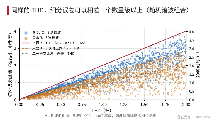
Conclusion: THD can only give a conservative upper bound on interpolation error; it cannot predict its magnitude.
Measurement one: constant-speed sampling FFT under speed ripple
When rotational speed fluctuates sinusoidally at frequency f_m with relative amplitude ε, the instantaneous signal frequency is f_0·(1 + ε·sin2πf_m·t) and the nth harmonic is phase-modulated with modulation index
β_n = n·ε·f_0 / f_m
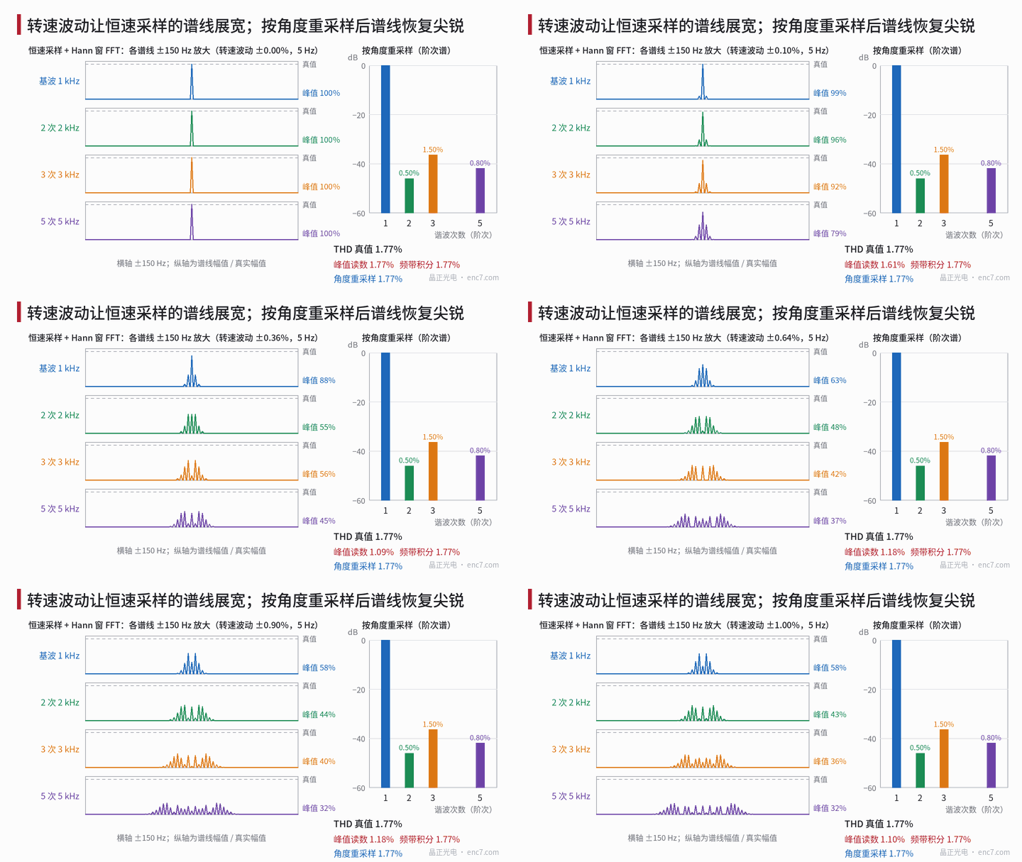
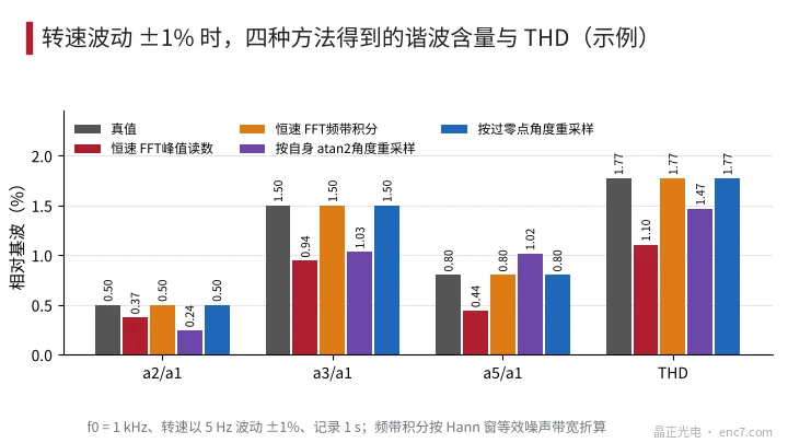
Each spectral line spreads into a Bessel comb spaced by f_m, with total width about 2n·ε·f_0; higher harmonics spread more. Worked example: f_0 = 1 kHz (2048 lines ≈ 29 r/min), ε = 1%, f_m = 5 Hz, so β is 2, 4, 6 and 10 for the fundamental and harmonics 2, 3 and 5. Reading peaks with a Hann-window FFT, the fundamental retains only 58% of its true value and harmonic 5 only 32%; the computed THD is 1.10%, 38% below truth; even at ε = 0.2% only 1.23% is read.
Under constant-speed sampling there are two remedies:
- Band power integration: with a Hann window (first sidelobe about −31 dB, rolling off at 18 dB/octave), sum the power within ±(n·ε·f_0 + 3f_m) of each line and divide by the equivalent noise bandwidth of 1.5 bins; in the example this recovers 1.77%. The cost is that noise inside the band is integrated too, so small harmonics are overestimated, and phase is lost.
- Window choice: when harmonics fall below −60 dB, Hann leakage may not be enough; a four-term Blackman–Harris window with lower sidelobes can be used; when only amplitude accuracy matters, a flat-top window is suitable.
Measurement two: angle-synchronous resampling
The proper cure is to synchronise sampling with angle so that each period contains an integer number of samples:
- Period markers: take the rising zero-crossing of A, one per period. Harmonic distortion is the same in every period and only shifts every zero-crossing by a fixed phase, so it does not warp the angle reference; a reference encoder’s counts can also be used.
- Angle interpolation: fit φ(t) with a cubic spline, provided speed changes little within one period.
- Resampling: take 64 points per period over an integer number of periods. Sample interpolation must use a high-order method such as a cubic spline; linear interpolation attenuates the nth harmonic by about sinc²(n·f_0/f_s), and with 51.2 raw samples per period harmonic 5 is about 3% low.
- FFT: a rectangular window is enough; each harmonic lands exactly on one bin and both amplitude and phase are obtained.
Do not use the signal’s own atan2 angle as the resampling reference. That angle already contains interpolation error and moves harmonic energy to other orders at first order: in the example the second reads 0.24%, the third 1.03%, the fifth 1.02%, THD 1.47% (see Figure 3).
In addition, measure the differential signal A = A+ − A− into the specified termination resistance and state the speed: when the front-end bandwidth is limited harmonic 5 is attenuated first at high speed, so THD falls with speed without the disc having improved.
Specification: write THD or quote each harmonic separately
THD is fine for a quick screen, but it discards the two pieces of information that decide interpolation error: which harmonic, and the phase relation between harmonics 3 and 5. A sounder wording separately limits a_2/a_1, a_3/a_1 and a_5/a_1, states differential, termination, speed, gap and temperature, and requires angle-synchronous resampling; when accuracy is what matters, specify the peak interpolation error and the amplitude of each order directly. Given only THD, estimate the worst case as e_peak ≤ 2·THD: THD ≤ 1%, 2048 lines, peak interpolation error no more than about 2.0″.
Engineering points
- State the THD denominator basis and whether noise is included; for encoder signals use the fundamental as denominator and exclude DC.
- The upper bound on peak interpolation error is (√2·a_2 + a_3 + a_5)/a_1, about 2·THD in the worst case; the lower bound can approach zero, so THD cannot replace an interpolation-error measurement.
- Constant-speed sampling FFT peak reading severely underestimates harmonics; at 1% speed ripple the example THD is about 38% low.
- Prefer angle-synchronous resampling: one zero-crossing marker per period, cubic-spline interpolation, integer periods, rectangular window.
- Do not use the signal’s own atan2 angle as the resampling reference; it changes the reading of each harmonic at first order.
- Quote harmonics 2, 3 and 5 and the test conditions separately; use THD only as a summary.
Summary
THD measures total harmonic content and relates to interpolation error only through an upper bound: at the same 1% THD, interpolation error can range from near zero to about 2% rad. Under speed ripple, constant-speed sampling broadens the spectral lines and peak readings fall markedly; using one zero-crossing per period as the angle reference and resampling by angle measures both amplitude and phase of each harmonic correctly. Quoting each harmonic and the test conditions in the specification is more useful than a single THD figure.
Translated from the ENC7 Chinese technical library (article 0265). Read the Chinese original. Need a disc built to your drawing? Request a quote or see our custom encoder discs.
© Langfang Jingzheng Optoelectronic Technology Co., Ltd. All rights reserved. This article was created with AI assistance.