Introduction to encoder principles
How an Optical Encoder Turns Light into Pulses

A beam of light, an encoder disc, a photodiode and a comparator are enough to turn shaft rotation into a train of countable pulses. This article follows the signal chain stage by stage: what the signal looks like at each stage, and why it is designed that way.
When a servo motor turns one revolution, the drive can count several thousand or even more than a million counts. Those counts do not appear from nowhere: an optical encoder has translated “rotation” into “pulses”. The translation is not mysterious; follow the light and it becomes clear.
First stage: light source and collimation
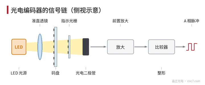
The signal chain starts with an LED, commonly infrared or red. Light from an LED diverges; if it fell directly on the disc, rays would pass the lines at different angles and the shadow would be blurred. So a collimating lens is usually placed in front of the LED, turning the light into a nearly parallel beam so that the “shadow” of the disc lines falls sharply on the detector behind.
Second stage: the disc modulates the light
The encoder disc is a circular plate with evenly distributed graduation lines. On a glass encoder disc, for example, the lines are chrome deposited on the glass and are opaque; the gaps between them are clear glass and transmit light. As the disc turns, the reading position alternates between “chrome line blocking the light” and “gap transmitting it”, and the intensity goes bright and dark accordingly.
However many lines the disc has, the intensity goes through that many bright–dark cycles in one revolution. A 2500-line disc therefore produces 2500 cycles per revolution.
Third stage: the index grating and the photodiode
The disc alone is not enough. Inside the readhead there is also a fixed index grating whose pitch matches that of the disc. As the disc turns, the lines of the two gratings alternately align (maximum transmission) and fall out of step (minimum transmission), so the total transmitted light varies periodically. The index grating lets many lines take part in the modulation at once, which strengthens the signal and also averages out small errors on individual lines.
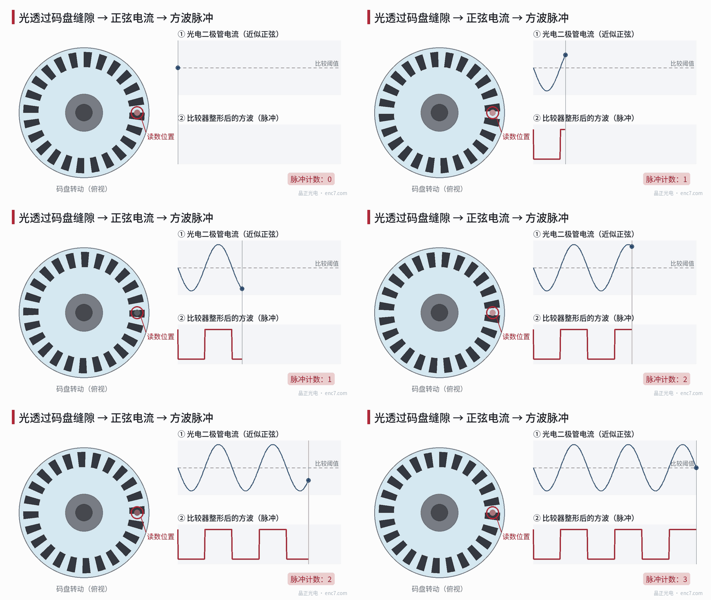
Light that has passed both gratings falls on a photodiode and produces a current proportional to the intensity. Because the lines have width, the light has some divergence, and diffraction has a smoothing effect, this current is not a hard square wave but a nearly sinusoidal waveform; see the upper part of Figure 1.
Fourth stage: amplification and squaring
The photodiode current is only of the order of microamperes and must first be turned into a voltage by a preamplifier. After that there are two approaches:
- Square-wave output: a comparator compares the sine signal with a threshold; above the threshold it outputs a high level, below it a low level, giving a square wave (lower part of Figure 1). The controller counts the square-wave pulses to know how far the shaft has turned.
- Sine/cosine output: the signal is not squared; the amplified sine and cosine signals are sent out as they are, and a later stage interpolates them. This can resolve several hundred or a thousand positions within one cycle and is used where high resolution is needed.
How much angle one cycle represents
The line count of the disc sets the angle that corresponds to one signal cycle:
| Disc line count | Angle per cycle | Angle per count after 4-fold decoding |
|---|---|---|
| 1000 | 0.36° | 0.09° |
| 2500 | 0.144° | 0.036° |
| 5000 | 0.072° | 0.018° |
The “4-fold decoding” here uses a second signal shifted by 90° (channel B): a count is taken on each rising and falling edge of A and B, so one cycle becomes 4 counts. The principles of direction sensing and of decoding will be treated in two other articles.
The disc sets the “foundation” of the signal
From this signal chain it is clear that later amplification, squaring and interpolation all work on the optical signal already modulated by the disc. Whether the lines are uniform, whether the edges are clean, whether the blocking is complete and whether the surface is clean directly decide the amplitude, contrast and consistency of the sine signal. If the disc is poorly made, later electronics can hardly make up for it. That is why encoder makers set strict requirements on line width, optical density, eccentricity and defects of the disc.
In brief
The working of an optical encoder can be summed up in four steps: the source emits light, the disc and the index grating modulate its intensity, a photodiode turns the light into a current, and a circuit squares that current into pulses or keeps the sine and cosine and sends them out. Once these four steps are clear, figures such as resolution, accuracy and interpolation have a clear origin.
Translated from the ENC7 Chinese technical library (article 0002). Read the Chinese original. Need a disc built to your drawing? Request a quote or see our custom encoder discs.
© Langfang Jingzheng Optoelectronic Technology Co., Ltd. All rights reserved. This article was created with AI assistance.