Introduction to encoder principles
How Encoder Signals Are Transmitted: TTL, HTL, Differential and Serial Protocols
The encoder sits on the motor and the controller in a cabinet, with a cable several metres long or longer in between, often next to inverters and power lines. How can the signal travel without being distorted? This article covers the interference immunity of single-ended and differential signalling, HTL levels, 1 Vpp sine/cosine, the general idea of serial protocols such as SSI and BiSS, and the effect of cable length.
The encoder is mounted at the rear of the motor, the controller in a cabinet, and a cable several metres long or longer runs between them. Next to the cable there are often the inverter output leads and the motor power leads, so electromagnetic interference is strong.
However clean the signals produced by the disc and the readhead may be, if interference is “added in” along the way, what the controller receives is wrong. Incremental counting also accumulates: one extra pulse and the position is off by one count for ever. So the encoder’s output interface is, in essence, a solution to “how to deliver the signal unchanged”.
Single-ended signals: interference mixes in directly
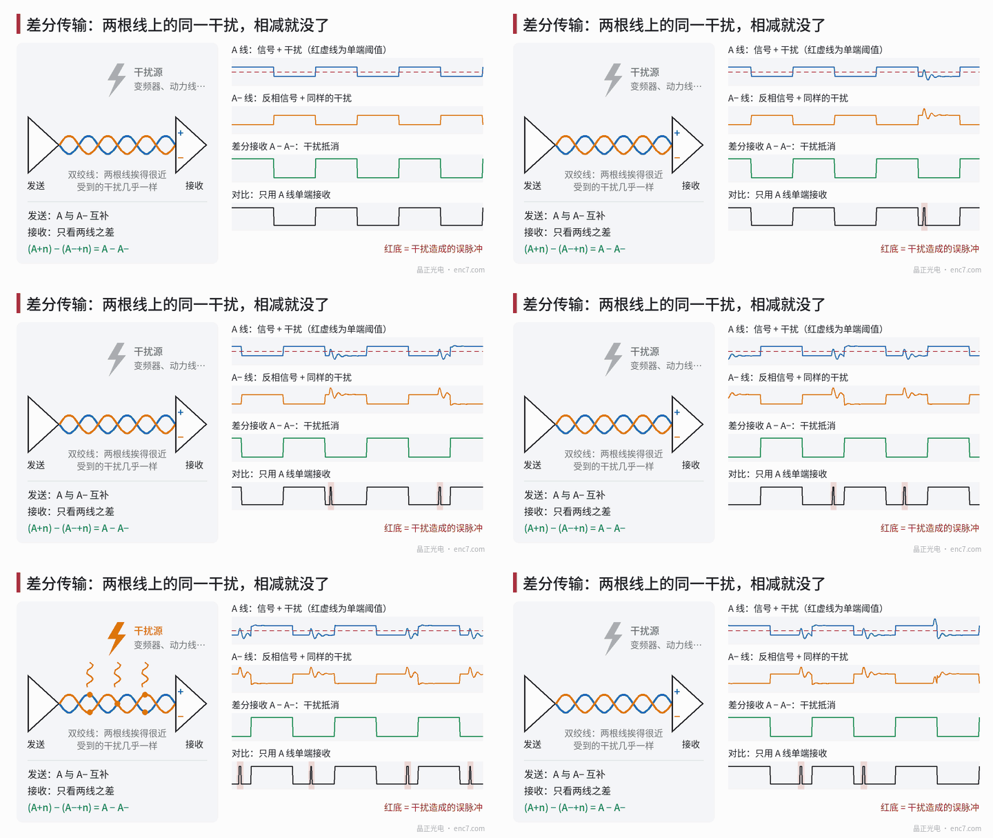
The simplest connection is single-ended: one wire per signal, referenced to the ground wire. Interference coupled onto the signal wire cannot be distinguished at the receiver from the signal itself; once the interference crosses the comparison threshold, pulses appear or disappear. See the bottom row of Figure 1. A difference in ground potential between the two ends can also cause false decisions. So single-ended signals are generally suitable only for short distances and low interference.
Differential signals: the interference is subtracted away
Differential transmission gives each signal a complementary line: A and A−, B and B−, Z and Z−. When A is high, A− is low. The two wires are twisted together, so the interference they pick up is almost identical.
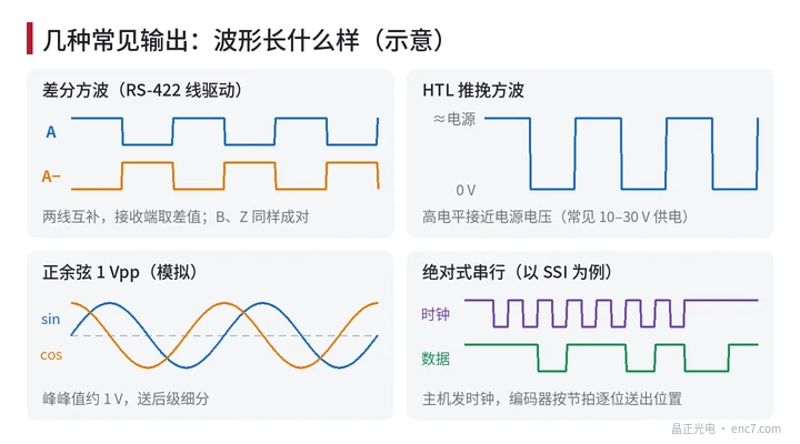
The receiver does not look at the voltage of each wire to ground; it looks only at the difference between the two wires: (A + interference) − (A− + interference) = A − A−. The interference cancels in the subtraction, while the signal, because of the subtraction, becomes twice the amplitude. This is an RS-422 line-driver output, and it travels farther than single-ended signalling.
When an encoder datasheet says “TTL output”, it often actually means this 5 V-powered RS-422 differential output; before wiring, check whether the complementary signals are present. Differential pairs must be connected as pairs and twisted as pairs; connecting only one wire is equivalent to falling back to single-ended.
HTL: a higher voltage against interference
HTL is a push-pull output, commonly supplied at 10–30 V, with the high level close to the supply voltage. The signal swing is large, so interference of the same size is a smaller fraction of it; immunity is good. It is often used on the factory floor, connected directly to the inputs of a PLC and similar equipment.
Sine/cosine 1 Vpp: leaving interpolation to the later stage
There is also a class of encoder that does not square the signals into square waves, but outputs analogue sine and cosine with a peak-to-peak amplitude of about 1 V, likewise often transmitted differentially, with interpolation done by the later-stage circuit. For example, 2048 lines with 1024-fold interpolation give about 2.10 million (210万) positions per revolution. Analogue signals are more sensitive to noise; cable shielding and length must follow the manual.
Absolute serial: SSI, BiSS and others
The position of an absolute encoder has a dozen to twenty-odd bits; a parallel output would need many wires, so serial communication is generally used, usually differential at the physical layer as well.
- SSI: the controller sends a burst of clock pulses, and the encoder shifts out the position data bit by bit from high to low in step with the clock; after one frame a short interval follows, then the next frame begins; see Figure 2.
- BiSS: also based on clock and data, with added error checking, and supports bidirectional communication so that encoder parameters can be read and written.
- There are also proprietary serial protocols from individual manufacturers; when selecting, confirm compatibility with the drive.
The effect of cable length
The longer the cable, the more problems appear:
- There is a voltage drop on the supply wires, and the voltage at the encoder may fall below the permitted range;
- Cable capacitance slows the signal edges, and the higher the pulse frequency, the shorter the cable that is allowed;
- In serial communication the signal takes time to travel to and fro on the cable, so the longer the cable, the lower the clock frequency usually has to be.
So for long-distance transmission, the supply voltage, the maximum output frequency and the communication rate must all be checked together, and a shielded twisted pair should be used, with the shield earthed as the manual specifies.
In brief
Single-ended signals are simple but vulnerable to interference; differential signals let the interference cancel in the subtraction and are the usual connection for incremental encoders; HTL relies on a large swing for immunity; sine/cosine 1 Vpp leaves interpolation to the later stage; absolute encoders mostly use serial protocols such as SSI and BiSS. The longer the cable, the more margin must be left on supply, frequency and rate.
Translated from the ENC7 Chinese technical library (article 0010). Read the Chinese original. Need a disc built to your drawing? Request a quote or see our custom encoder discs.
© Langfang Jingzheng Optoelectronic Technology Co., Ltd. All rights reserved. This article was created with AI assistance.