Custom discs
How to Set Encoder Disc Outer Diameter, Bore and Thickness

Disc dimensions are not something to back-calculate casually from the space in the housing. A more sensible order: first set the read radius from line count and pitch, then add track and edge margins to get the outer diameter, set the bore from the shaft and assembly method, set the thickness from substrate, stiffness and weight, and finally mark the pattern side and the concentricity datum clearly. This article goes through each item in that order.
When designing a new encoder, how should you fill in OD, bore and thickness on the disc drawing? A common approach is to look at the space left in the housing and back-calculate the OD. A smoother approach is to start from the read radius and settle each item from the inside out, in the order shown in Figure 1.
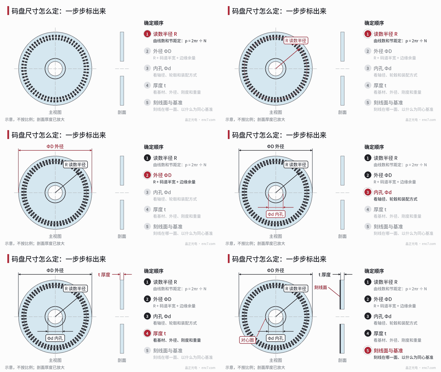
Step 1: read radius
The read radius is the radius at the centre of the track, where the readhead looks. It is set by line count and pitch: p = 2πr ÷ N, or conversely r = N × p ÷ 2π.
For example, for a 2,500-line disc with about 50 μm pitch, r ≈ 2,500 × 50 μm ÷ 6.283 ≈ 19.9 mm, so about 20 mm. The index grating in the readhead is often designed for a particular read radius, so the two must match.
A larger radius has another benefit: lower sensitivity to eccentricity. For the same 5 μm eccentricity, the error is about 52″ at radius 20 mm and about 103″ at radius 10 mm (Δθ ≈ e ÷ r).
Step 2: outer diameter
OD ΦD = 2 × (read radius + half track width + edge margin).
- Track width: must cover the height of the reading window, plus margin for assembly eccentricity and radial runout;
- Edge margin: cutting and edge grinding leave tiny chips at the edge, and handling and clamping also use the edge, so lines must not be too close to it.
A worked example (numbers for illustration only): read radius 20 mm, track width 2 mm, edge margin 1.5 mm gives an OD of about 2 × (20 + 1 + 1.5) = 45 mm.
Do not enlarge the OD casually. A solid disc’s moment of inertia is J = ½mR², and mass is itself proportional to R², so at the same thickness doubling the OD multiplies inertia by 16 — bad for a small motor’s dynamic response.
Step 3: bore
The bore depends on shaft diameter and assembly method:
- Bonded to a hub: the bore is slightly larger than the hub’s locating step to leave room for adhesive; during assembly the disc is centred under a microscope using the centring ring, not by the bore fit;
- Hollow-shaft designs: the bore must leave room for the shaft and is often very large, so the ring between track and bore becomes narrow;
- Located by the bore: if assembly centres directly on the bore, specify the concentricity between bore and track explicitly.
Leave a bonding area between bore and track as well, so adhesive cannot spread onto the track.
Step 4: thickness
Thickness balances stiffness, weight and space. A thicker glass disc is sturdier and less prone to edge chipping, but heavier with more inertia; metal discs can be very thin; discs with a large OD and small thickness need more attention to flatness.
For transmissive discs also note: which face carries the pattern affects the distance from the lines to the index grating. With the pattern face toward the readhead, the read gap is not affected by the glass thickness.
Step 5: pattern side and datum
Once the dimensions are set, the drawing should also state clearly:
| Item | What to specify |
|---|---|
| Read radius | Radius of track centre; the readhead is designed to it |
| OD ΦD | Size and tolerance; whether it is a locating datum |
| Bore Φd | Size and tolerance; concentricity if centred by the bore |
| Thickness t | Size and tolerance; flatness requirement |
| Pattern side | Which face carries the pattern, facing readhead or light source |
| Concentricity datum | Centring ring, bore or OD as the datum |
Summary
The order for setting disc dimensions is: read radius → OD → bore → thickness → pattern side and datum. The read radius is calculated from line count and pitch; the OD adds track and edge margins to it; the bore follows the assembly method; thickness follows substrate and stiffness. Think it through in this order, then confirm process feasibility with the disc manufacturer, and the drawing is far less likely to need rework.
Translated from the ENC7 Chinese technical library (article 0019). Read the Chinese original. Need a disc built to your drawing? Request a quote or see our custom encoder discs.
© Langfang Jingzheng Optoelectronic Technology Co., Ltd. All rights reserved. This article was created with AI assistance.