Encoder-disc terminology
Index Repeatability: Definition and Error Breakdown
Index repeatability is the scatter of the trigger position over repeated passes through the index. This article separates unidirectional from bidirectional and σ from range, breaks it into four terms—noise, speed and delay, thermal drift and count quantisation—shows that in a 2500-line example the ungated σ is about 2.3″ and about 9″ once speed and thermal drift are added, and gives a method for collecting Z trigger positions against a high-resolution reference.
The same machine homes again and again: sometimes it returns to the same count, sometimes it is one count off. Measure it another way and the “index repeatability” in the report changes from “0 counts” to “σ = 4″”. Index repeatability looks like a single statistic, but it is the sum of several physical mechanisms and is very sensitive to the statistical basis. This article first pins down the definition and the basis, then splits it into four terms, and finally gives a measurement method.
Definition: unidirectional or bidirectional, σ or range
Index repeatability is the scatter of the Z trigger position, relative to a high-resolution position reference, over repeated passes through the index. It is not the index offset (the fixed difference between electrical and mechanical zero): the offset can be calibrated, repeatability cannot. Nor is it index drift over long periods and wide temperature ranges; the specification should list these separately.
Unidirectional and bidirectional. Unidirectional repeatability counts only trigger positions in one direction of rotation on one edge; bidirectional repeatability pools both directions and also contains the difference caused by latching different edges in the two directions (see the article on index position in forward and reverse rotation in this library), so it is usually much larger.
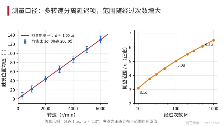
σ or range. For a normal distribution the expected range (maximum − minimum) grows with the sample count M: about 3.1σ at M = 10, about 5.0σ at M = 100 and about 6.5σ at M = 1000. Write only “range ≤ x” without M and the same readhead can be reported with numbers that differ by a factor of two.
Conditions. Speed (or speed range), direction, edge, temperature, gated or not, and whether power is cycled before each pass must all be stated.
Error breakdown: four terms
The trigger position can be written as
x = x_0 + n/s + v·t_d + Δx_T + quantisation
where x_0 is the nominal position, n the electrical noise at the comparator input, s the slope of the index signal at the threshold crossing, v the velocity, t_d the delay and Δx_T the thermal drift. The example uses 2500 lines (one signal period is 518.4″; after fourfold decoding 1 count is 129.6″); the analog index signal is taken as a Gaussian peak with a full width at half maximum of 450° electrical and a threshold at 50% of peak.
1. Noise: σ_x = σ_V / s. The slope at the threshold crossing is about 0.00308·V_p per electrical degree. With electrical noise σ_V = 0.5%·V_p, σ_x ≈ 1.62° electrical, about 2.3″. For a gated Z the edge is set by A/B; the slope at the A/B zero crossing is π/180·amplitude per degree, so the same 0.5% noise gives only about 0.41″. Filtering in front of the comparator lowers σ_V but adds delay—which is exactly the next term.
2. Speed and delay: Δx = v·t_d. t_d is the delay difference between the Z trigger path and the position-sampling path, including comparator, logic, cable and capture circuit. If Z and A/B take the same path and the controller latches the A/B count, the delays cancel; if the position comes from sampled sine/cosine interpolation while Z goes through a separate comparator path, the delay difference remains. With t_d = 1 μs at 3000 r/min (18 000°/s), Δx = 64.8″. At constant speed this is only a fixed offset that can be calibrated; if the homing speed varies within ±10%, it becomes a scatter of ±6.5″. If the capture circuit is synchronised to a 50 MHz clock, ±20 ns of clock jitter corresponds to about ±1.3″ at 3000 r/min.
3. Thermal drift: Δx_T = ΔV / s. With a fixed threshold and an index amplitude that falls with temperature, the threshold-crossing point moves. In the example a 10% amplitude drop delays the rising edge by about 25.6″ (mechanism and countermeasures: see the article on index thermal drift in this library). If the temperature changes during the test, this term widens the distribution and looks like poorer repeatability.
4. Count quantisation. If the controller latches an ungated Z with the fourfold-decoded count, it reads the count in which the edge falls. When the whole trigger distribution lies inside one count, it shows “0 counts”; when it straddles a count boundary, the reading jumps between two adjacent values. With the mean at a distance d from the nearest count boundary, the jump probability is about Φ(−d/σ); at d = 3σ it is about 0.13%. For a gated Z the edge is itself a count edge, so as long as the latch logic has no race condition, the latched value is deterministic.
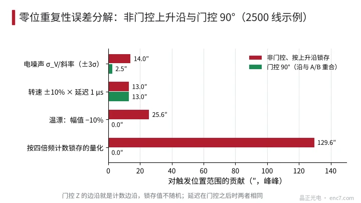
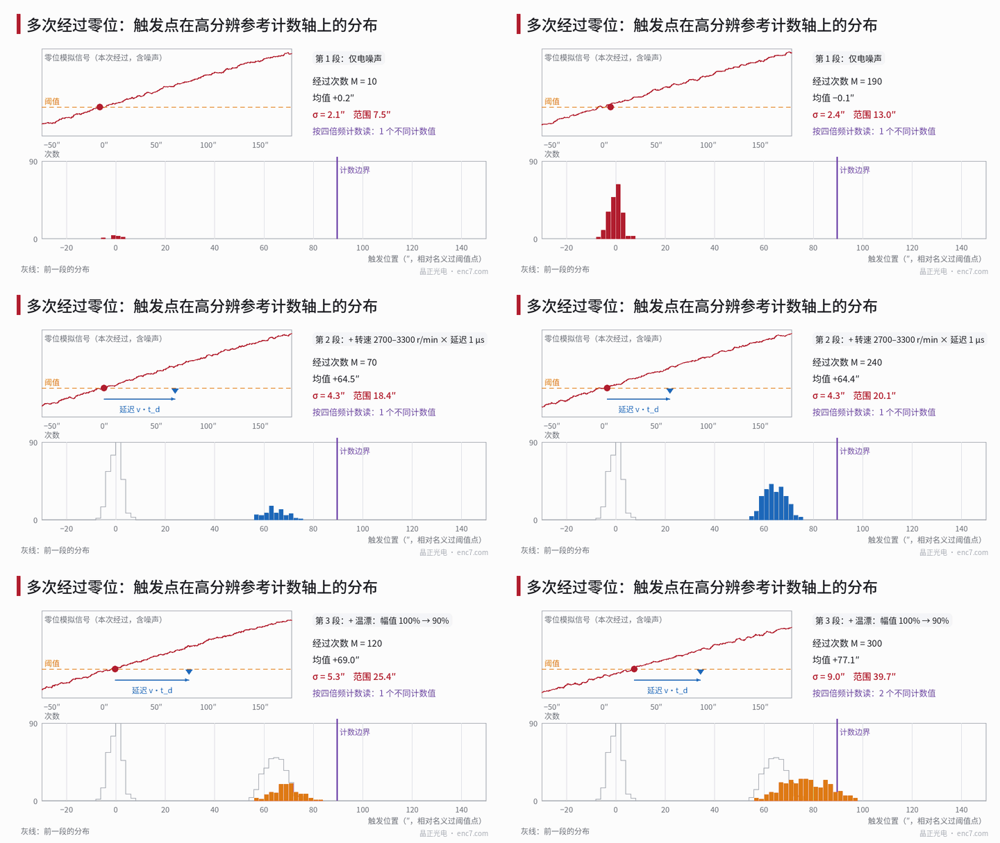
When combining, random terms add by root-sum-square and drift terms by their actual range of variation. In the example, noise of 2.34″ and the speed term (uniform ±6.5″, σ ≈ 3.7″) combine to σ ≈ 4.4″; adding a linear 10% amplitude drift (σ ≈ 7.4″) gives about 8.6″, consistent with the 9.0″ from the simulation in Figure 1.
Measurement method and basis
- Setup: mount the encoder (or disc plus readhead) on a smooth-running spindle, drive it at constant speed and let it reach full thermal equilibrium.
- Reference: use high-factor interpolation of the encoder’s own sine/cosine signals (for example 1000 points or more per period, about 0.5″ at 2500 lines), or a coaxial reference encoder. The reference resolution should be no coarser than one fifth of the expected σ. The index track and the incremental track are on the same disc, so eccentricity and graduation error are common to both; interpolation error at the index is only a fixed offset and does not affect the scatter.
- Capture: latch the reference position in hardware on the rising and on the falling edge of Z separately, with a known, fixed capture delay.
- Samples: at least 100 passes per condition; the relative standard error of the σ estimate is about 1/√(2M), about 7% at M = 100.
- Separation: in one direction, measure at around 5 speeds, plot the mean against speed and fit a straight line: the slope is t_d and the intercept is the static position (see Figure 3); then repeat with the other direction and at other temperatures.
- Report: σ and range (with M), direction, edge, speed, temperature, gated or not.
The most common mistake is to use the controller’s fourfold-decoded count directly as the reference. At 2500 lines 1 count is 129.6″, far larger than a true scatter of a few arcseconds; a result of “0 counts” or “±1 count” shows how far the trigger point is from a count boundary, not the repeatability itself.
Engineering points
- State in the specification: unidirectional or bidirectional, σ or range (with sample count M), speed, temperature, edge and gating; list index offset and index repeatability separately.
- Estimate the noise term as σ_V/slope; raising the slope of the index signal (multi-slit code patterns, gating to the A/B edge) is more effective than filtering alone.
- Keep the homing speed fixed; where variable speed is unavoidable, measure the delay difference t_d and compensate for speed.
- Thermal drift masquerades as poor repeatability: reach thermal equilibrium before measuring repeatability, and measure thermal drift separately in a climatic chamber.
- When an ungated Z is latched with the count, place the nominal trigger point in the middle of a count, more than 3σ from a boundary; the probability of a one-count jump is then about 0.13%.
- The measurement reference should be at least 5 times finer than the expected σ; do not use the fourfold-decoded count to evaluate repeatability at arcsecond level.
Summary
Index repeatability is the scatter of the trigger position over repeated passes through the index, and its value depends on the basis: unidirectional or bidirectional, σ or range, and sample count. It breaks down into four terms—noise σ_V/slope, speed and delay v·t_d, thermal drift ΔV/slope, and count quantisation. Gating locks the edge to A/B and removes thermal drift and quantisation, but not the delay difference. Collecting trigger positions against a high-resolution reference at several speeds separates the terms and gives repeatability figures that can be compared.
Translated from the ENC7 Chinese technical library (article 0268). Read the Chinese original. Need a disc built to your drawing? Request a quote or see our custom encoder discs.
© Langfang Jingzheng Optoelectronic Technology Co., Ltd. All rights reserved. This article was created with AI assistance.