Encoder-disc terminology
Index Width: Spatial Width, Electrical Angle and Gating Basis
Index width can be stated as spatial width, mechanical angle, electrical angle, time or counts. This article gives the conversion table, derives the ungated-Z width change ΔW ≈ 2ΔV/slope with threshold and amplitude, explains the margin conditions for 90°, 180° and 360° gating, separates width from index-position accuracy with a worked example, and lists common confusions in data sheets.
The data sheet writes “Z width 90°”, the incoming-inspection report writes “Z width 2.1 μs”, and the customer drawing marks a 25 μm index slit—three numbers that may describe the same thing or may not match at all. Index width has several representations; ungated and gated outputs are set by entirely different mechanisms; and a more common misunderstanding is to treat a pass on width as a pass on index position. This article sorts these bases out one by one.
Five bases and their conversion
Let the line count be N, the read radius r, the pitch p = 2πr/N, the rotational speed n (r/min) and the incremental-signal frequency f = N·n/60. Taking electrical angle W_e (one incremental-signal period = 360°) as the reference:
- Mechanical angle: W_m = (W_e/360°) × (1 296 000″/N)
- Spatial width (at the read radius): w = (W_e/360°) × p
- Time: τ = W_e / (360°·f)
- fourfold counts: W_e / 90°
Conversion for 2500 lines, r = 20 mm, 3000 r/min (f = 125 kHz):
| Electrical angle | Mechanical angle | Spatial width | Time | fourfold counts |
|---|---|---|---|---|
| 90° | 129.6″ | 12.6 μm | 2.0 μs | 1 |
| 180° | 259.2″ | 25.1 μm | 4.0 μs | 2 |
| 360° | 518.4″ | 50.3 μm | 8.0 μs | 4 |
With interpolated output one must also ask which period “electrical angle” refers to. After 10× interpolation of a 2500-line disc the output A/B period is 51.84″; “gated 90°” referring to the output period is only 12.96″, or 0.2 μs at 3000 r/min—10× narrower than the raw-period reading. Time width is also affected by comparator and output-stage delay and therefore varies with speed; see the article on Z-pulse width versus speed in this library.
The index slit width on a drawing is not equal to the output width either. By geometric projection, a disc slit of width a correlated with an index window of width b (a ≥ b) yields a trapezoid of top a − b and base a + b; at the 50% threshold the width equals a exactly. With a = 25 μm and b = 25 μm one obtains a triangle of base 50 μm and a 50%-level width of 25 μm (about 180° electrical); at other thresholds the width differs.
Ungated Z: width set by signal shape and threshold
Ungated Z is the result of comparing the index analogue signal V_z(θ) with a threshold V_th; its width is the distance between the two threshold crossings. A threshold change ΔV moves each edge by ΔV/slope, so
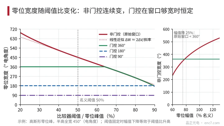
ΔW ≈ ΔV/|s_left| + ΔV/|s_right| = 2ΔV/s (when the two slopes are equal)
where s is the slope at the threshold crossing (V/° electrical). With a fixed threshold and a relative amplitude change a of the index peak, the equivalent threshold change is ΔV = −a·V_th.
Worked example (illustrative): a Gaussian index peak of FWHM 450° electrical, threshold at 50% of peak. The slope at the threshold is about 0.00308·V_p/°; a threshold change of 10% of peak changes the width by about 65° (exact +67°/−64°); with the threshold held and amplitude down 20%, the width falls from 450° to 371°. Source ageing, temperature, gap change and contamination all change amplitude, so ungated width is not a fixed value (see Figure 2).
Gated Z: clipped to 90°, 180° or 360°
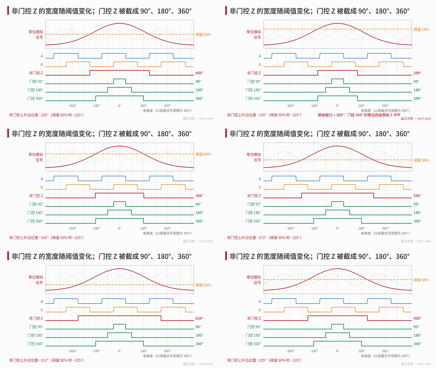
Gated Z is the logical AND of the raw index window with a window derived from A and B: the quadrant where A and B are both high is 90°, the high half-period of one channel is 180°, and one full period is 360°. As long as the raw window fully covers the gate window, the output width is fixed and both edges coincide with A/B edges. The condition is
W_raw ≥ W_gate + 2·|alignment error| + margins on both sides
In the example the raw window is 450°: 90° gating has 180° of margin per side; 360° gating has only 45° per side. When amplitude falls by about 25% the raw window shrinks to about 344°, the two edges of 360° gating are then set by the raw Z, and both width and position move with it. A narrower gate gives more margin but a shorter time width and a higher speed requirement on the receiver.
Width and index-position accuracy are not the same thing
Width specifies how long the pulse is, not where it sits. Index position depends on which feature the receiver uses for locating: the rising edge, the centre, or “a particular A/B state while Z is high”.
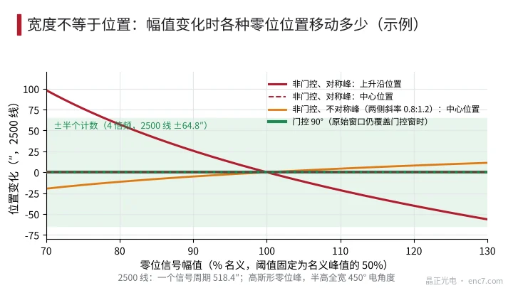
- Ungated, rising-edge location: a width change ΔW moves the rising edge by ΔW/2. In the example a 20% amplitude drop moves the rising edge back by 39.7° electrical, about 57″ at 2500 lines—nearly half a count.
- Ungated, centre location: with a symmetric peak the centre does not move; with unequal side slopes (example 0.8:1.2) the centre does move, about −20″ when amplitude falls to 70%.
- Gated: position is locked to A/B edges, so neither width nor position changes with amplitude. But once the raw window drifts outside the margin, the gate may pick the neighbouring quadrant or neighbouring period; the output width is still 90°, yet the position has jumped by 90° or 360° electrical.
In bidirectional use, forward and reverse latch different edges and the two directions’ index positions differ by one width; see the bidirectional-index article of this library. A pass on index width therefore only means the pulse length is acceptable; index position must be specified separately through repeatability and position relative to A/B.
Common confusions in data sheets
- “Width 90°” without stating electrical angle, or without stating whether it is the raw period or the interpolated output period, can be wrong by the interpolation factor;
- ungated width given only as a typical value, without threshold, amplitude and temperature conditions;
- time width without stating speed, or without stating whether the measurement point is at the output or at the receiver;
- “1 count wide” and “90°” are equal only under fourfold (quadrature) decoding referred to the raw period;
- treating the drawing’s index slit width as the output width;
- substituting a width tolerance for an index-position tolerance.
Engineering points
- State index width primarily as “electrical angle (naming which signal period)”, and when mechanical angle or time is added, state the line count, interpolation factor and speed.
- Ungated width varies with threshold and amplitude, ΔW ≈ 2ΔV/slope; the specification must give the threshold ratio, amplitude range and temperature range.
- Before gating, check the margin: at lowest amplitude and highest temperature the raw window must still cover the gate window plus twice the alignment error.
- For ungated Z located on the rising edge, position drift equals half the width change; when index accuracy is required, switch to gating or to centre location.
- Index slit width, index-window width and threshold together set the output width; the drawing slit width cannot be taken directly as the output width.
- Specify index position and repeatability separately; do not substitute a width tolerance.
Summary
Index width has five bases—electrical angle, mechanical angle, spatial width, time and counts—and conversion requires a clear line count, interpolation factor and speed. Ungated width is set by the index-signal shape and the threshold and varies continuously with amplitude; gated width is clipped to 90°, 180° or 360°, but only while the raw window retains margin. Width and index position are independent metrics: a stable width does not imply a stable position, and a width change need not move the position—write both separately in the specification.
Translated from the ENC7 Chinese technical library (article 0267). Read the Chinese original. Need a disc built to your drawing? Request a quote or see our custom encoder discs.
© Langfang Jingzheng Optoelectronic Technology Co., Ltd. All rights reserved. This article was created with AI assistance.