Glass & substrate science
Measuring CTE: Pushrod Dilatometer vs Laser Interferometry
Pushrod dilatometers and laser interferometry measure the same expansion coefficient – where do their capabilities differ? Taking a 50 mm specimen heated by 100 K, this article calculates the elongation of various materials, sets up an uncertainty budget, compares the suitability of both methods for soda-lime, borosilicate, fused silica and zero-expansion materials, and shows how to choose for incoming-material verification.
In incoming-material verification for code discs, the expansion coefficient is the hardest item to verify yourself: borosilicate glass is often specified as 3.3 ± 0.2, fused silica as 0.5, and zero-expansion materials to within ±0.02 (all in 10⁻⁶/K). The “resolution” in an instrument manual is the number of digits of the length sensor, whereas the uncertainty of α is determined jointly by the baseline, the temperature and the optical path – the two often differ by one or two orders of magnitude. This article compares the pushrod dilatometer (methods of the ASTM E228 type) and laser interferometry (methods of the ASTM E289 type) within the same uncertainty budget.
How large is the quantity to be measured
The mean linear expansion coefficient is defined as
α_m = ΔL / (L₀·ΔT)
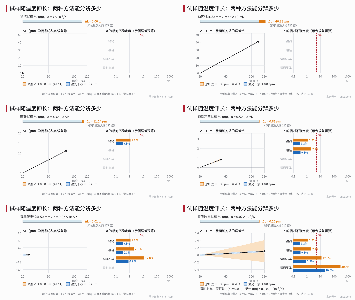
where L₀ is the specimen length at the reference temperature and ΔL the change in length caused by the temperature change ΔT. With L₀ = 50 mm and ΔT = 100 K:
| Material | α (10⁻⁶/K) | ΔL |
|---|---|---|
| Zero-expansion type (example) | 0.02 | 0.1 μm |
| Fused silica | 0.5 | 2.5 μm |
| Borosilicate glass | 3.3 | 16.5 μm |
| Soda-lime glass | 9 | 45 μm |
| Stainless steel | 16.5 | 82.5 μm |
| Polycarbonate | 70 | 350 μm |
The uncertainty propagates as u(α)² = (u_ΔL/(L₀·ΔT))² + (α·u_ΔT/ΔT)²; the error of the specimen length (10 μm on 50 mm is only 0.02 %) can be neglected. The first term is an “absolute” error independent of the material; the second is proportional to α. The smaller α is, the more the first term dominates – which is why zero-expansion materials are hard to measure.
Pushrod method: baseline and temperature are the bottleneck
In the pushrod method one end of the specimen rests against a holder, and the other end transmits the elongation through a pushrod to a displacement sensor (commonly an LVDT). The pushrod and the holder themselves also expand with temperature, so a baseline must first be measured with a reference specimen of known expansion and then subtracted from the specimen reading. The digital resolution of the sensor itself can reach the nanometre level, but the residual of the baseline correction and non-uniform heating of the pushrod make the total uncertainty of ΔL typically a few tenths of a micrometre. Taking an example value of ±0.30 μm (growing linearly with ΔT) and a temperature uncertainty of 1 K (the temperature difference between thermocouple and specimen),
δα(baseline) = 0.30 μm / (50 mm × 100 K) = 0.06×10⁻⁶/K
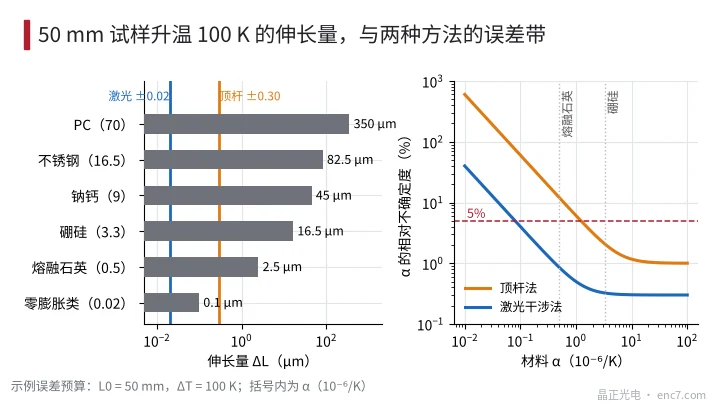
independent of the material. For soda-lime glass with α = 9 it accounts for only 0.7 %; the temperature term of 0.09 dominates, giving a total of ±0.108, about 1.2 %. For borosilicate at 3.3 the total is ±0.069, about 2.1 %, sufficient to verify a tolerance of ±0.2 (about ±6 %). For fused silica at 0.5 the total is ±0.060 and the relative error rises to 12 %, so 0.5 can no longer be distinguished from 0.45.
Laser interferometry: the wavelength as the scale
In laser interferometry the end face of the specimen (or a mirror attached to the specimen) becomes one reflecting surface of a Michelson or Fabry–Pérot interferometer. With a He-Ne laser at 632.8 nm, each displacement change of λ/2 ≈ 316 nm passes one fringe; subdividing the fringe to 1/100 gives a resolution of about 3 nm. The specimen can sit in an isothermal block without a pushrod, so there is essentially no pushrod baseline problem.
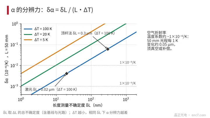
Its new problem comes from the optical path: the temperature coefficient of the refractive index of air is about −1×10⁻⁶/K, so for a 50 mm optical path each 1 K change alters the optical path by about 0.05 μm (single pass, doubled for a round trip) – the same order as the 0.02 μm target. Vacuum, refractive-index compensation or a reference beam path is therefore required. Taking ±0.02 μm and a temperature uncertainty of 0.3 K (specimen in the isothermal block), δα(baseline) = 0.004×10⁻⁶/K, i.e. 4×10⁻⁹/K, consistent with the claim of “the order of 10⁻⁸/K”. The resolution formula is
δα = δL / (L₀·ΔT)
As shown in Figure 3: to measure α to 1×10⁻⁹/K with L₀ = 50 mm and ΔT = 100 K requires δL = 5 nm; with ΔT of only 20 K, the same δL = 0.02 μm yields only 0.02×10⁻⁶/K. Measuring materials near their zero crossing often calls for a narrower temperature range and a smaller δL.
Uncertainty budget and choosing a method for incoming verification
With the example budget (L₀ = 50 mm, ΔT = 100 K):
| Material | Pushrod u(α) | Laser u(α) | Choice |
|---|---|---|---|
| Soda-lime 9 | ±0.108 (1.2 %) | ±0.027 (0.3 %) | Pushrod is enough |
| Borosilicate 3.3 | ±0.069 (2.1 %) | ±0.011 (0.3 %) | Pushrod is enough |
| Fused silica 0.5 | ±0.060 (12 %) | ±0.0043 (0.9 %) | Laser |
| Zero-expansion type 0.02 | ±0.060 (300 %) | ±0.0040 (20 %) | Laser only |
For larger α, the relative error of the laser method is set by the temperature term (0.3 K over 100 K), no longer by length; further improvement requires better temperature uniformity. For soda-lime and borosilicate glass the pushrod uncertainty is already far below the tolerance, so there is no need to switch to a more expensive method.
Engineering notes
- First distinguish the resolution of the length sensor from the uncertainty of α; the latter is determined by baseline, temperature and optical path, and the supplier should be asked for a budget.
- For soda-lime and borosilicate glass with tolerances of ±0.2 or wider, a pushrod dilatometer with reference specimens is sufficient; there is no need to insist on laser interferometry.
- For materials with α < 1, such as fused silica and glass-ceramics, the absolute error of the pushrod method (about 0.06) is already of the same order as α; choose laser interferometry.
- A longer specimen or a wider temperature range lowers δα as 1/(L₀·ΔT) and improves resolution, but the result then has to be converted with the variation of α with temperature.
- An expansion coefficient must always be reported with its temperature range: for glass this is usually the mean over 20–300 ℃, whereas the actual operating range of a disc is narrower; the two cannot be used interchangeably.
- The laser method needs vacuum or refractive-index compensation: over a 50 mm optical path each 1 K change in air temperature corresponds to a spurious elongation of about 0.05 μm.
- For incoming material from the same batch a comparison method can be used: specimen and reference sample measured simultaneously in the same furnace, so the difference is little affected by common-mode errors.
Summary
The real figure of merit of a dilatometer is the uncertainty of α, made up of the two terms u_ΔL/(L₀·ΔT) and α·u_ΔT/ΔT. The baseline error of the pushrod method is about 0.06×10⁻⁶/K – enough to verify soda-lime and borosilicate glass, but not to resolve materials below 0.5. The length term of laser interferometry is only 4×10⁻⁹/K, suitable for fused silica and zero-expansion materials, provided the optical path and temperature uniformity are controlled. For incoming verification, simply choose the method according to the α of the material.
Translated from the ENC7 Chinese technical library (article 0565). Read the Chinese original. Need a disc built to your drawing? Request a quote or see our custom encoder discs.
© Langfang Jingzheng Optoelectronic Technology Co., Ltd. All rights reserved. This article was created with AI assistance.