Industry applications in depth
Measuring gantry angle on a CT scanner: large ring discs above 700 mm ID
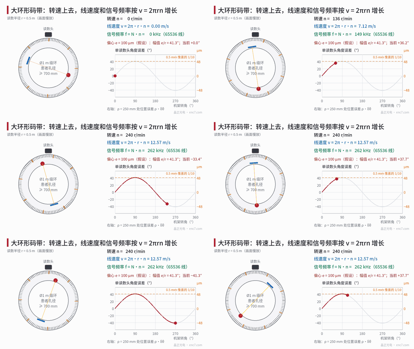
A fast CT gantry turns in 0.25 s per revolution. At a read radius of 0.5 m the linear speed is 12.6 m/s and the signal frequency is several hundred kHz. This article derives the requirements on frequency and sampling synchronization, converts angular error into position error in the field of view, and estimates the magnitude of three large-ring errors: eccentricity, segment joints and thermal mismatch.
On a CT scanner the X-ray tube and the detectors are mounted on a rotating gantry. A patient has to pass through the middle, so the aperture is at least a little over seven hundred millimetres, and on a fast machine one revolution takes only 0.25–0.3 s. The encoder disc therefore becomes a large ring about 1 m in diameter: a complete glass disc will not fit, and the scale has to be made as a continuous steel tape or as a code strip joined from several segments. The linear speed is also much higher than on a typical servo encoder disc. This article works through, for that duty, speed and frequency, sampling synchronization, the conversion of angular error, and the error sources that belong to the large ring itself. All figures are examples.
Speed and signal frequency
Linear speed and rotational speed are related by
v = 2π·r·n
where r is the read radius and n is the number of revolutions per second. At r = 0.5 m and 0.25 s/rev (4 r/s, 240 r/min), v = 12.57 m/s; at 0.3 s/rev it is 10.47 m/s. The signal frequency is f = v/p = N·n, where p is the pitch of the code strip and N is the line count around the full circle.
| Pitch p | Full-circle line count (r = 0.5 m) | Signal frequency at 0.25 s/rev |
|---|---|---|
| 100 μm | 31 416 | 126 kHz |
| 47.9 μm | 65 536 | 262 kHz |
| 40 μm | 78 540 | 314 kHz |
| 20 μm | 157 080 | 628 kHz |
Take 65 536 lines: after fourfold quadrature decoding there are 262 144 counts per revolution, 4.94″ per count, and the interval between counts is about 0.95 μs. A few hundred kHz is not severe for the front end of the readhead, but the finer the pitch, the tighter the gap tolerance and the harder it is to control the graduation error around the full circle. A large ring therefore usually takes a coarser pitch and makes up the angular resolution by interpolation. In addition the centripetal acceleration on the gantry is ω²r ≈ 316 m/s², about 32 g, and the bonding or clamping of the code strip must be verified for that load.
Sampling synchronization: how many counts correspond to one view
Suppose there are 1024 views per revolution (an assumption). Then each view occupies 262 144/1024 = 256 counts, the view interval is 0.35°, and at 0.25 s/rev this is about 244 μs. An integer number of counts makes it convenient to trigger directly from the encoder pulses. The angular quantization of the trigger is 4.94″ for 1 count, which at ρ = 250 mm converts to 6 μm and can be ignored.
More attention is needed for jitter of the trigger delay, which converts to angle with rotational speed:
δθ = ω·δt
At ω = 25.13 rad/s, 1 μs of jitter corresponds to 25 μrad (5.2″) and 10 μs to 52″. Whether the encoder triggers the acquisition directly, or acquisition is triggered in time and the angle of each view is recorded afterwards, the jitter of the delay must be held to a few microseconds.
How angular error becomes image error
If each view has an angular error δθ in the reconstruction, the position at a distance ρ from the centre of rotation is offset by ρ·δθ. Assume an isocentre pixel of 0.5 mm, a field radius of 250 mm, and a requirement that the position error at the edge of the field must not exceed 0.1 pixel (an assumed internal figure), that is 50 μm:
δθ ≤ 50 μm / 250 mm = 200 μrad ≈ 41.3″
This includes the entire angular-measurement error. A slowly varying error that is synchronous with the rotation angle turns the geometry of all views as a whole; irregular jumps from view to view make the projections in different directions mutually inconsistent, and the latter is usually less acceptable. See Figure 3: an error of 41.3″ is exactly 50 μm at ρ = 250 mm and only 20 μm at ρ = 100 mm. For CT, therefore, angular resolution is readily sufficient; what is difficult is full-circle accuracy and repeatability.
Three error sources of the large ring
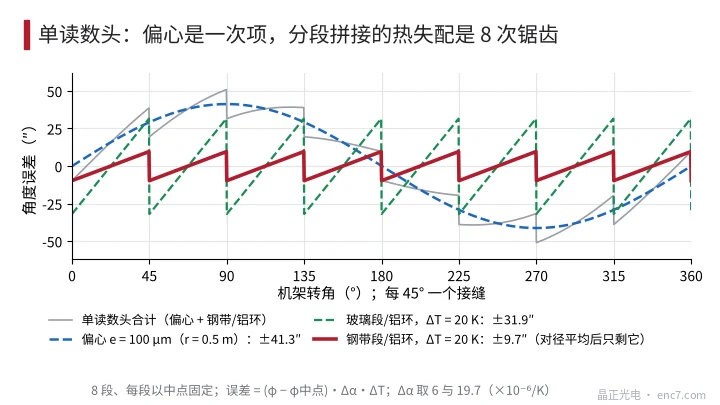
Eccentricity. For a single readhead the amplitude of the first-order error is e/r. If the centre of the code-strip ring is offset by 100 μm from the gantry axis and r = 0.5 m, this is 200 μrad, or 41.3″, which already uses the entire budget. The relative accuracy of a large ring is not high, and the absolute eccentricity is hard to keep small, so a pair of diametrically opposite readheads (180° apart) is commonly averaged. That cancels the first-order term and all odd-order errors.
Joints and segments. A position error δ at a joint of a segmented code strip becomes a local angular error δ/r directly: 5 μm corresponds to 2.1″ and 10 μm to 4.1″. The error of an 8-segment jointed scale has an 8th-order period and is even-order, so diametrically opposite readheads do not cancel it either; it has to be controlled by jointing accuracy and by calibration.
Thermal mismatch. A uniform temperature rise does not change the angular position of the complete ring, but the radius changes: at r = 0.5 m and ΔT = 20 K the change is about 170 μm for a steel ring and about 230 μm for an aluminium ring, and the read gap changes with it. The readhead must be mounted on a member with the same thermal expansion. What actually produces an angular error is the difference Δα in the coefficients of expansion of the segments and the base ring. If each segment is fixed only at its mid-point, the error within the segment is
δθ = (φ − φ_mid)·Δα·ΔT
where φ is the angular position within the segment; for 8 segments, φ − φ_mid is at most ±22.5° (0.393 rad).
| Combination (8 segments, ΔT = 20 K) | Δα (×10⁻⁶/K) | Error within a segment |
|---|---|---|
| Steel tape on a steel ring | about 0 | about 0 |
| Steel tape on an aluminium ring (17 and 23) | 6 | ±9.7″ |
| Borosilicate-glass segments on an aluminium ring (3.3 and 23) | 19.7 | ±31.9″ |
The single item of glass segments on an aluminium ring already takes three quarters of the 41.3″ budget, so the material of the large-ring code strip and that of the base ring must be chosen as a pair, with closely matched coefficients of expansion preferred.
Engineering points
- First compute the highest frequency from v = 2πrn and f = N·n, then check the readhead bandwidth; a large ring should take a coarser pitch and make up the resolution by interpolation.
- Convert the position error at the edge of the field into an angular specification: δθ = allowed position error / ρ; the example of 50 μm and 250 mm corresponds to about 41″.
- Choose the number of views as a divisor of the counts per revolution, so that each view contains an integer number of counts, and hold the jitter of the trigger delay to a few microseconds.
- Use diametrically opposite readheads to cancel eccentricity, and at the same time calibrate the 8th-order class of error at the joints; list this item separately in the budget.
- Keep the coefficients of expansion of the code strip and the base ring as close as possible; measure the position error at the joints, and do not rely on the drawing alone.
- Verify bonding and clamping under the centripetal acceleration of 32 g, and make the readhead bracket stiff, so that resonance does not cause a periodic change of the gap.
In brief
The difficulty of a large-ring encoder disc for CT is not resolution, but the high linear speed of 0.25 s per revolution, the full-circle accuracy after conversion by ρ·δθ in the field of view, and the three errors peculiar to a large ring: eccentricity, jointing and thermal mismatch. Working the allowed position error back into an angular specification, and then allocating the budget among these three items, is what gives a basis for the choice of design.
Translated from the ENC7 Chinese technical library (article 0772). Read the Chinese original. Need a disc built to your drawing? Request a quote or see our custom encoder discs.
© Langfang Jingzheng Optoelectronic Technology Co., Ltd. All rights reserved. This article was created with AI assistance.