Custom discs
Multi-Track Gray Code Layout: Track Order, Inner/Outer Assignment and Minimum Code Element

A Gray code element is 2πr/2ⁿ, yet the bars of the least significant bit are 2 elements wide. For a Φ40 disc with 10 bits and the LSB at r = 18 mm, the element is about 110 μm, the finest bar about 221 μm and the track band about 4.85 mm wide. This article compares placing the LSB on the outside and on the inside, derives the reading misalignment between tracks, and gives a parameter table and ordering rules.
A Φ40 disc is to provide 10-bit singleturn absolute position: 1024 positions per revolution, each about 21.1′. With multi-track Gray code, each of the 10 tracks carries one bit, and the detectors are lined up along one radial line and read simultaneously. Before drawing the layout, four questions must be answered: how wide is the narrowest feature, which bit goes on the outside, how wide is the annular band occupied by the 10 tracks, and how accurately must the read line be aligned. This article works through each item using Φ40 and 10 bits as the example.
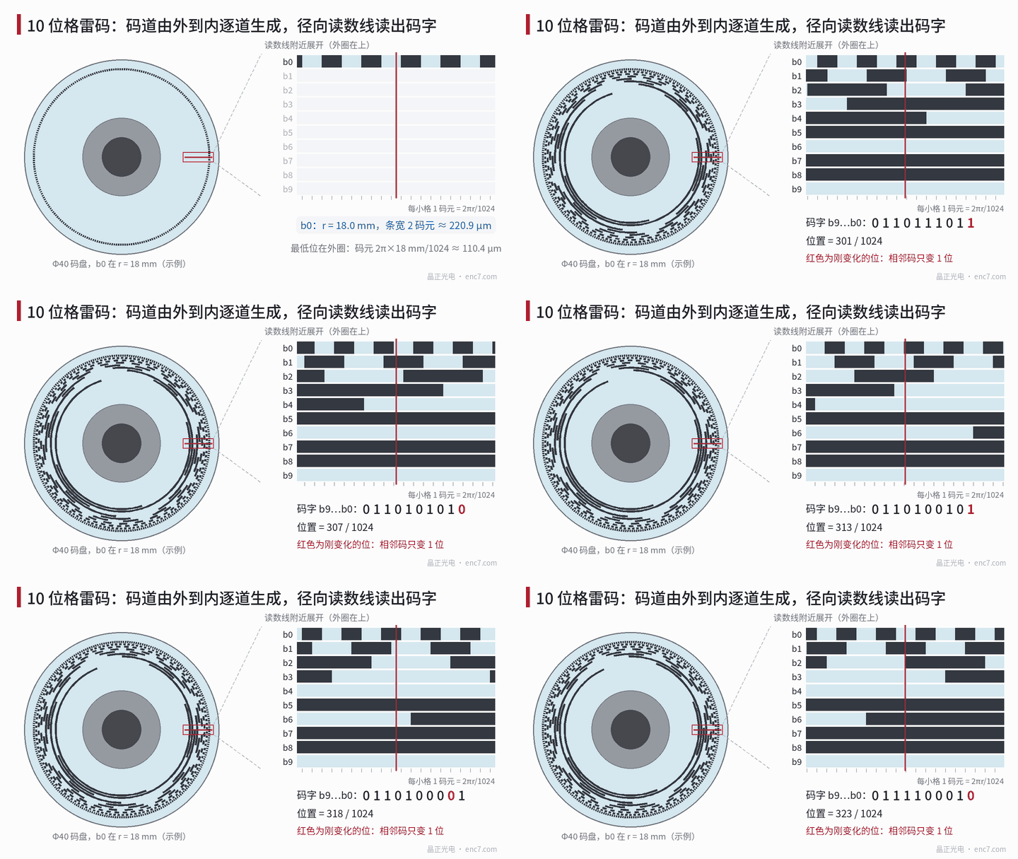
Pattern of each track: bar width and number of transitions
Gray code is obtained from binary B as G = B XOR (B » 1), so bit k is G_k = B_k XOR B_(k+1). Let the angular width of a code element (one position quantisation unit) be 360°/2ⁿ; its arc length at radius r is
q = 2πr / 2ⁿ
Writing out the bits one by one gives:
- track k (k ≤ n − 2) has bright and dark bars each 2^(k+1) elements wide, a period of 2^(k+2) elements, and 2^(n−k−1) transitions per revolution;
- the MSB b(n−1) is bright for half a revolution and dark for the other half; the next bit b(n−2) is also half-revolution, but offset 90° from the MSB;
- the transitions of all tracks per revolution add up to exactly 2ⁿ, and every element boundary carries exactly one transition — this is what “adjacent codes differ in only one bit” means.
This leads to an easily overlooked conclusion: the bright and dark bars of the LSB are 2 elements wide, not 1. Only in natural binary code is the LSB bar 1 element wide. So the “minimum element 2πr/2ⁿ” is the unit of position resolution, while the finest line in the pattern is 2q. In addition, the LSB track itself is a uniform grating of 2^(n−2) periods — 256 periods for 10 bits.
Layout parameters for a 10-bit Φ40 disc
Example layout: b0 at r = 18 mm, track width W = 0.35 mm (radial size of the detection window plus allowance for eccentricity and mounting; see the track radial width article of this library for how to choose it), gap between tracks 0.15 mm, track pitch P = 0.5 mm, b9 at 13.5 mm. The track band runs from 13.325 mm to 18.175 mm, about 4.85 mm wide. At r = 18 mm the element is q ≈ 110.4 μm, i.e. 1265.6″.
| Track | Radius (mm) | Bar width (elements) | Bar angle | Bar arc length | Transitions per rev |
|---|---|---|---|---|---|
| b0 | 18.0 | 2 | 0.70° | 220.9 μm | 512 |
| b1 | 17.5 | 4 | 1.41° | 429.5 μm | 256 |
| b2 | 17.0 | 8 | 2.81° | 834.5 μm | 128 |
| b3 | 16.5 | 16 | 5.63° | 1.62 mm | 64 |
| b4 | 16.0 | 32 | 11.25° | 3.14 mm | 32 |
| b5 | 15.5 | 64 | 22.5° | 6.09 mm | 16 |
| b6 | 15.0 | 128 | 45° | 11.8 mm | 8 |
| b7 | 14.5 | 256 | 90° | 22.8 mm | 4 |
| b8 | 14.0 | 512 | 180° | half revolution | 2 |
| b9 | 13.5 | 512 | 180° | half revolution, offset 90° from b8 | 2 |
LSB on the outside or on the inside
If the order is reversed, b0 falls at 13.5 mm and the bar width shrinks with the radius. Comparison (for 13 bits the track pitch is unchanged and the innermost track is at 12 mm):
| Item | b0 outside | b0 inside |
|---|---|---|
| 10-bit b0 bar width | 220.9 μm | 165.7 μm |
| 13-bit b0 bar width | 27.6 μm | 18.4 μm |
| Radial distance to the outer incremental track (assumed at 18.5 mm) | about 0.5 mm | about 5 mm |
| Reading misalignment between b0 and incremental track at 20 μm eccentricity | about 6″ | about 83″ |
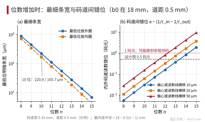
At 10 bits both arrangements give wide bars; the difference is not whether they can be made, but two other points. First, signal margin: the readhead penumbra and the detection window width are fixed lengths, so the narrower the bar, the harder it is for the LSB signal to reach full bright and full dark, and the more the edge position depends on the threshold. Assuming a penumbra width of about 20 μm, at 13 bits with the LSB inside the b0 bar is already narrower than that. Second, synchronisation with the incremental track: an absolute encoder with interpolation must stitch the phase of the Gray code LSB to the incremental track (stitching tolerance in another article of this library), and their reading misalignment under eccentricity is proportional to e·(1/r_a − 1/r_b); placing them next to each other makes it about 13 times smaller than having the whole track band in between.
Placing the LSB on the inside is only worth considering when the detector arrangement of the reading chip is already fixed, or the outer ring must be kept free for other tracks.
Read-line alignment: the wider the track band, the larger the misalignment
The fault tolerance of Gray code is this: as long as the angular scatter of the reading points of the individual tracks is less than 1 element, the reading is always one of two adjacent codes and the error does not exceed 1 element; with half of this kept as design margin, the target is 0.5 element. The scatter has three sources:
- eccentricity e: Δφ_e = e·(1/r_in − 1/r_out)·|sinθ|
- lateral offset d of the read line (detector line parallel to the radius but not passing through the centre): Δφ_d = d·(1/r_in − 1/r_out)
- rotation γ of the read line (about radius r_p): Δφ_γ ≈ γ·r_p·(1/r_in − 1/r_out)
where r_in and r_out are the radii of the innermost and outermost tracks. All three terms are proportional to 1/r_in − 1/r_out, approximately the track band width divided by r², independent of track order. In this example 1/13.5 − 1/18 ≈ 0.0185 mm⁻¹ and 1 element is 6.14 mrad; 0.5 element corresponds to e or d of about 0.17 mm and to γ of about 0.6° (r_p = 15.75 mm). At 10 bits, eccentricity and lateral offset are thus very relaxed, while the rotation of the readhead is the item that actually needs control: a rotation of 0.5° uses up about 0.41 element.
As the number of bits increases, the element halves with each extra bit while the track band gains one more track, so the scatter grows quickly (see Figure 2). With 10 μm of eccentricity or lateral offset, 13 bits use about 0.36 element and 14 bits about 0.82 element. On Φ40, pure multi-track Gray code is generally taken to about 13 bits; beyond that, synchronised stitching with the incremental track or a single-track code is needed.
Track ordering rules
- Arrange monotonically by bit weight: b0 outside, MSB inside, no skipping in between, so that the bar width changes together with the radius.
- If there is an incremental track, put it outermost with b0 directly inside it, leaving only the crosstalk gap between them.
- Put the two half-revolution tracks on the innermost rings; with only two transitions each, they are the least sensitive to radius and eccentricity.
- Choose the track pitch at the lower limit of track width plus crosstalk gap; the narrower the track band, the larger the read-line tolerance.
- Give the element boundary angles of every track exactly as 2πm/2ⁿ and form them in the same writing pass or on the same photomask, to avoid angular misalignment between tracks.
Engineering takeaways
- Distinguish element and line width: element q = 2πr/2ⁿ, the finest Gray code bar is 2q; for Φ40, r = 18 mm and 10 bits these are 110.4 μm and 220.9 μm.
- Put the LSB outside: at 10 bits the bar width grows from 165.7 μm to 220.9 μm, and the eccentricity misalignment with the outer incremental track is about 13 times smaller.
- Calculate the track band width first: 10 tracks at 0.5 mm pitch give about 4.85 mm, innermost track at 13.5 mm; bore and hub must fit inside this.
- At 10 bits the tightest assembly item is read-line rotation: about 0.6° already uses 0.5 element, whereas eccentricity and lateral offset can be relaxed to about 0.17 mm.
- Estimate the bit-count limit from the misalignment: at e = 10 μm, 13 bits use about 0.36 element and 14 bits about 0.82 element; beyond that, switch to synchronised stitching or a single-track code.
- Before releasing the layout, scan one full revolution element by element and check that adjacent codes differ in only one bit and that the total number of transitions per revolution equals 2ⁿ.
Summary
The position unit of Gray code is 2πr/2ⁿ, but its finest line is twice that. Putting the LSB outside gives the widest bars and makes synchronisation with the incremental track easier; track order does not change the read-line misalignment, which depends only on track band width and radius. For Φ40 and 10 bits the pattern dimensions are very relaxed and what really needs control is readhead rotation; at higher bit counts, the track band width becomes the limit.
Translated from the ENC7 Chinese technical library (article 0301). Read the Chinese original. Need a disc built to your drawing? Request a quote or see our custom encoder discs.
© Langfang Jingzheng Optoelectronic Technology Co., Ltd. All rights reserved. This article was created with AI assistance.