Glass & substrate science
Optical Inhomogeneity of Glass: How Striae and Refractive-Index Variations Affect Phase-Based Readout

Refractive-index variation Δn in glass gives transmitted light an optical path difference OPD = Δn·t. With Δn = 10⁻⁵ and 1–2 mm thickness this is only 10–20 nm, negligible for amplitude-type readout; in diffractive interferential readout the two beams pass through different locations and acquire a phase difference, worst case about 1–2″ (example). This article derives the homogeneity requirement.
“Transparency” and “homogeneity” of glass are two different things: a glass that absorbs no light at all can still carry internal refractive-index variations of 10⁻⁵ or more, caused by uneven composition during melting (in the form of striae), a non-uniform annealing temperature field and stress. The traditional view is that “this only matters for imaging optics; an encoder disc need not care”. For opaque (light-blocking) patterns that is essentially true, but as soon as the readout depends on the phase of the light, things change. This article first calculates the optical path difference and wavefront distortion, then looks separately at how amplitude-type and diffractive interferential readout are affected, and finally works back from the angular error budget to a homogeneity requirement.
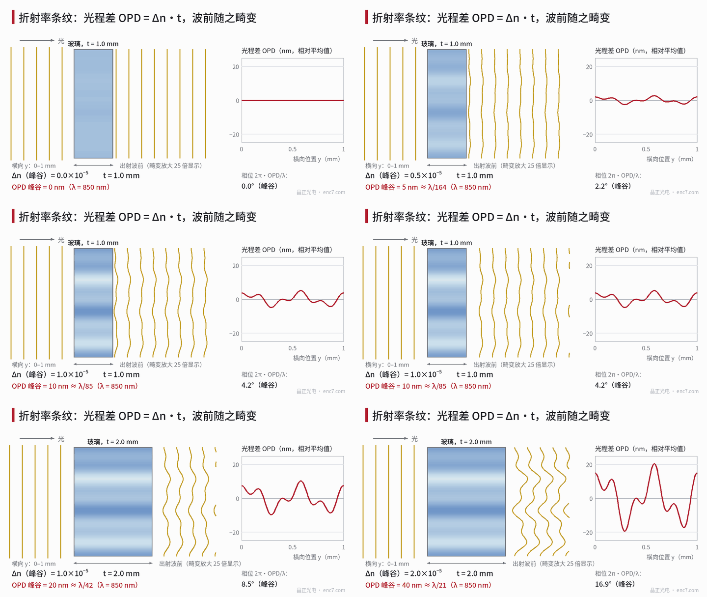
Model: optical path difference and wavefront
Let light travel through glass of thickness t along the thickness direction, with the refractive index varying with lateral position y as n(y) = n₀ + Δn(y). The optical path difference and phase at each point of the wavefront are then
OPD(y) = Δn(y) · t, φ(y) = 2π · OPD(y) / λ
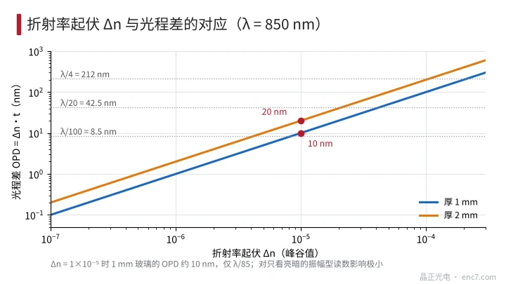
where Δn is the peak-to-valley value and λ the wavelength. For Δn = 10⁻⁵ and λ = 850 nm:
- t = 1 mm: OPD = 10 nm, about λ/85, phase peak-to-valley 4.2°;
- t = 2 mm: OPD = 20 nm, about λ/43, phase peak-to-valley 8.5°.
For reference, λ/4 is 212 nm. A uniform shift of the whole wavefront has no effect on the reading; only its lateral variation matters: the wavefront slope dOPD/dy deflects rays, and the OPD difference between two points makes their phases differ (Figure 2).
Amplitude-type readout: deflection is tiny
Let the striae vary as a cosine with period Λ_s and amplitude Δn/2; the maximum ray deflection angle is then πΔn·t/Λ_s. With Λ_s = 0.1 mm, t = 1 mm and Δn = 10⁻⁵ the deflection is 3.1×10⁻⁴ rad (about 65″). With the pattern on the entrance face and a gap g = 0.1 mm from the glass exit face to the index grating, the image shifts by 31 nm, only 0.16% of a 20 μm pitch, or about 0.3″ at r = 20 mm; for Λ_s = 1 mm it is only 3 nm. Bright/dark contrast is unaffected, so Δn of order 10⁻⁵ can be ignored for amplitude-type readout.
Diffractive interferential readout: the two beams see different glass
Diffractive readout relies on recombining the ±1st-order beams. For a grating of pitch p the diffraction angle inside the glass is sinθ_g = λ/(n·p), and after passing through thickness t the two beams are separated by
s = 2t · tanθ_g
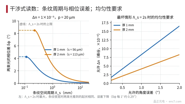
For p = 20 μm, n = 1.51 and λ = 0.85 μm, sinθ_g = 0.028; s = 56 μm for t = 1 mm and 113 μm for t = 2 mm. Since the two beams pass through different locations, the phase difference depends only on the difference of the glass at those two locations:
δφ = (2π/λ) · Δn · t · |sin(πs/Λ_s)|
The worst case is a stria period Λ_s = 2s, where δφ = 2πΔn·t/λ (i.e. the phase peak-to-valley above). The phase difference between the two beams is equivalent to a grating displacement x = δφ·p/(4π), converted to angle as x/r. Worked example (Δn = 10⁻⁵, p = 20 μm, r = 20 mm, example):
| Thickness | Worst case (Λ_s = 2s) | Λ_s = 1 mm | Λ_s = 10 mm |
|---|---|---|---|
| 1 mm | 4.2°, 1.2″ | 0.75°, 0.21″ | 0.07°, 0.02″ |
| 2 mm | 8.5°, 2.4″ | 2.9°, 0.84″ | 0.30°, 0.09″ |
The effect is largest when the stria period is comparable to the beam separation; with very wide striae both beams fall on the same spot and the error vanishes quickly. As the disc rotates the striae sweep across the beam path, so the error is not a simple harmonic but follows the distribution inside the glass (Figure 3, left). At the same time, phase variation of the wavefront within the light spot lowers interference contrast: with a phase rms of 0.1 rad it drops only by about 0.5%, which is less important than the phase error itself. In addition, the phase corresponding to the groove depth of a phase grating, 2π(n−1)d/λ, changes only with the relative change of n, Δn/(n−1), about 2×10⁻⁵, so it has almost no effect on zero-order efficiency.
How to set the homogeneity requirement
From the displacement budget x = e·r (e is the allowed angular error in radians) and the worst case δφ = 2πΔn·t/λ:
Δn_max = 2 · e · r · λ / (p · t)
For e = 0.5″, r = 20 mm and p = 20 μm: t = 1 mm requires Δn ≤ 4.1×10⁻⁶, t = 2 mm requires 2.1×10⁻⁶; relaxing e to 1″ gives 8.2×10⁻⁶ and 4.1×10⁻⁶ respectively. The limit is proportional to e and r and inversely proportional to p and t: the finer the pitch and the thinner the glass, the looser the requirement. Homogeneity of optical materials is graded per ISO 10110-4; high-grade types reach the 10⁻⁶ level, while ordinary float glass generally does not guarantee this parameter.
Engineering points
- Amplitude-type readout (opaque pattern + index grating) is insensitive to Δn; a separate homogeneity specification is generally unnecessary.
- For diffractive interferential or phase-based readout, work back with Δn_max = 2·e·r·λ/(p·t), considering thickness and pitch together.
- Sensitivity is highest when the beam separation s is comparable to the stria period; fine striae 0.1–0.5 mm wide are more dangerous than large-area gradual variation.
- When selecting material, write the homogeneity grade and test method (transmitted-wavefront measurement by interferometer) into the specification; do not just write “optical grade”.
- Go as thin as possible: the error is proportional to t, so reducing 2 mm to 1 mm relaxes the requirement by a factor of two.
- With the pattern on the exit face, so that light passes through the glass first and diffracts afterwards, the two beams do not separate inside the glass and the shear error is greatly reduced; this can serve as a basis for the design choice.
Summary
For glass with Δn = 10⁻⁵, a thickness of 1–2 mm produces only 10–20 nm of optical path difference, negligible for opaque-pattern amplitude readout. In diffractive interferential readout the two beams pass through different locations; the phase difference is capped at 2πΔn·t/λ, worst case about 1–2″ with the example parameters, and the homogeneity requirement worked back from this is of order 10⁻⁶. Whether homogeneity needs to be specified depends on the readout principle, not on whether the glass looks transparent.
Translated from the ENC7 Chinese technical library (article 0575). Read the Chinese original. Need a disc built to your drawing? Request a quote or see our custom encoder discs.
© Langfang Jingzheng Optoelectronic Technology Co., Ltd. All rights reserved. This article was created with AI assistance.