Industry applications in depth
Parallel picking robots: encoder bandwidth at 150 picks per minute
A parallel picking robot performing 150 pick-and-place cycles per minute is limited on the active arm by acceleration, not by rotational speed. From a gate-shaped trajectory this article calculates arm-side peaks of 8.5 rad/s and 419 rad/s², derives the delay error ω·T_d and the residual ½α·T_d² after compensation, and gives the requirements on the communication cycle, interpolation bit depth and the stiffness of the disc bond.
A typical specification for a parallel picking robot is 150 pick-and-place cycles per minute, a period of 0.4 s, each cycle first lifting 25 mm, traversing 305 mm, then descending 25 mm. The rotational speed of the active arms is not high, but acceleration and reversal have to be completed within a few tens of milliseconds, so the angular acceleration is large. The meaning of encoder bandwidth then changes: it is not signal frequency, but the delay from sampling the data to using them.
From the gate-shaped trajectory to the joint: ω and α
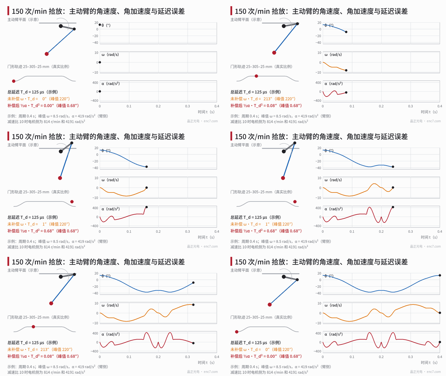
Take a planar simplified model of a single active arm (example parameters): base radius 0.20 m, moving-platform radius 0.05 m, active arm a = 0.30 m, passive arm b = 0.80 m, and the picking plane 0.6 m below the shoulders. Outbound travel 0.2 s: the 305 mm horizontal motion follows a fifth-order polynomial, and the first and last 1/4 of the time are used to complete the 25 mm lift and descent; the return travel is the time reversal. Numerical derivatives of the inverse kinematics, for the arm that lies in the plane of motion, give:
- the arm angle swings between +12.6° and −37.4°, a span of 50°;
- a peak angular velocity of 8.5 rad/s (81 r/min), occurring near the midpoint of the outbound travel;
- a peak angular acceleration of 419 rad/s², occurring in the later part of the outbound travel, where descent and transverse deceleration overlap.
The other two arms are about 4.7 rad/s and 312 rad/s². The tip peak velocity is about 2.9 m/s and the acceleration about 7 g. With a reduction ratio i = 10, the motor-side peak speed is 814 r/min and the angular acceleration is 4191 rad/s². At 814 r/min a 2048-line encoder disc has a signal frequency of only 27.8 kHz; the restriction on line count comes from elsewhere.
Delay error: two formulae
Let the total delay from sampling the position data to their use by the controller be T_d, and let the arm angle be θ(t). If the old data are used directly, the error is
θ(t) − θ(t − T_d) ≈ ω·T_d
If a first-order extrapolation with velocity is used for compensation, what remains after the Taylor expansion is
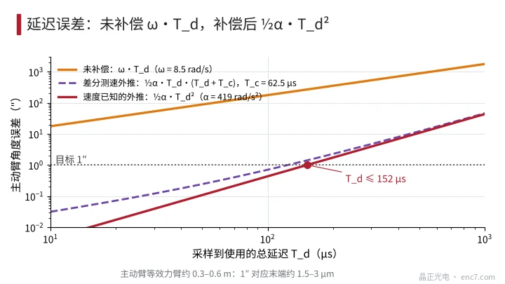
e = ½·α·T_d²
where ω and α are the arm angular velocity and angular acceleration. The longer the delay and the larger the acceleration, the more necessary the compensation becomes:
| T_d | Uncompensated ω·T_d | Compensated ½α·T_d² |
|---|---|---|
| 62.5 μs | 110″ | 0.17″ |
| 125 μs | 220″ | 0.68″ |
| 250 μs | 440″ | 2.7″ |
| 500 μs | 880″ | 10.8″ |
The equivalent moment arm of an active arm is about 0.3–0.6 m; 220″ corresponds to 0.3–0.6 mm at the tip, and 0.68″ after compensation is about 1–2 μm. Aiming at a residual ≤ 1″, T_d ≤ √(2·1″/α) = 152 μs. If velocity is obtained by two-point difference, the velocity itself lags by half a sample period and the residual becomes ½·α·T_d·(T_d + T_c), where T_c is the sample period. At T_c = 62.5 μs, T_d must be brought down to 124 μs.
Requirements on the communication cycle, interpolation and line count
Communication cycle: T_d includes the maximum age of the data (one communication cycle) plus interface transfer and processing time. A 62.5 μs cycle plus 60 μs of transfer and processing is about 122 μs, which just meets the 124 μs above; if the cycle is relaxed to 250 μs, even after compensation the error is 2.7″ or more.
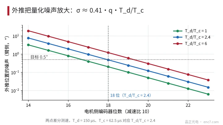
Interpolation bit depth: extrapolation amplifies quantization noise. The velocity noise of a two-point difference is σ_v ≈ 0.41·q/T_c, and after extrapolation to T_d the position noise it introduces is 0.41·q·T_d/T_c. When T_d/T_c = 2.4, to keep the arm-side noise below 0.5″ the motor-side q must be no greater than 0.5″ × 10 / (0.41 × 2.4) = 5.1″, i.e. at least 18 bits (4.9″) (Figure 3). At 2048 lines, an interpolation factor of 128 already reaches 18 bits, and the demand on signal quality is very low.
Line count: the frequency is only 27.8 kHz, so line count is not limited by front-end bandwidth and can be chosen according to signal quality, pitch and cost; a high line count need not be pursued.
Reciprocating vibration: the joint between disc and hub
The motor-side encoder disc undergoes an angular acceleration of 4191 rad/s² with the rotor, about 4×10⁷ reversals per year (estimated at 2.5 cycles per second, 16 h per day and 300 days per year). Taking a Ø30 mm glass encoder disc, 1 mm thick, with a Ø8 mm bore, the mass is 1.64 g, the moment of inertia J = 2.0×10⁻⁷ kg·m², and the peak inertial torque is 8.3×10⁻⁴ N·m. With a bond ring of radius 5 mm, width 2 mm and adhesive thickness 50 μm, the shear stress is only about 2.6 kPa, far below the strength of the adhesive, so fatigue is not the main risk.
What really affects accuracy is the torsional compliance of the bond layer. The torsional stiffness is k_t = G·A·r²/h, and the lag of the disc relative to the hub is φ = J·α/k_t:
| Adhesive | Shear modulus | Motor-side lag | Referred to the arm | Resonance frequency |
|---|---|---|---|---|
| Rigid epoxy | 1.2 GPa | 0.005″ | negligible | about 69 kHz |
| Flexible adhesive | 50 MPa | 0.11″ | 0.01″ | about 14 kHz |
| Silicone | 0.5 MPa | 10.9″ | 1.09″ | about 1.4 kHz |
The frequency of the acceleration change is only a few hertz to a few tens of hertz, far below resonance, so the lag can be calculated as quasi-static. The lag of a disc bonded with soft silicone is already of the same order as the 1″ target, and it varies with acceleration, so it cannot be subtracted by a single calibration; an adhesive of medium modulus or higher can be neglected.
Engineering takeaways
- First obtain the arm-side peak ω and α from the trajectory, then back-calculate the total delay T_d from e = ½·α·T_d² ≤ the target.
- T_d includes the communication cycle, transfer and processing; when velocity is measured by difference, include the T_c term as well; the cycle should preferably not exceed 62.5 μs.
- Interpolate to 18 bits or more on the motor side, size the extrapolation noise from q·T_d/T_c, and note that the noise halves for each 1 bit added.
- Line count is decided by signal quality and pitch; a frequency of 27.8 kHz puts no pressure on the front end.
- Bond the encoder disc with an adhesive of medium modulus or higher, and check φ = J·α/k_t; soft silicone produces an arcsecond-scale lag under high acceleration.
- Position at critical instants such as the grasp should use data latched at the same instant, so that different delays on the axes do not produce a tip deviation.
Closing
For a picking robot in high-acceleration reciprocation, what is required of the encoder is a low and stable delay: delay sets the error, and after compensation the residual is ½α·T_d², with T_d bounded at the 150 μs scale. A communication cycle of about 62.5 μs, interpolation to 18 bits or more on the motor side, and a medium-modulus disc bond are enough to hold the encoder-related dynamic error within 1″; signal frequency, by contrast, is not the limit.
Translated from the ENC7 Chinese technical library (article 0765). Read the Chinese original. Need a disc built to your drawing? Request a quote or see our custom encoder discs.
© Langfang Jingzheng Optoelectronic Technology Co., Ltd. All rights reserved. This article was created with AI assistance.