Encoder-disc terminology
Pattern Distortion Components: Translation, Scale, Ellipse and Twist

Distortion of an encoder-disc pattern relative to its ideal position can be decomposed into translation, rotation, uniform scaling, ellipse, twist and higher-order terms. This article writes the tangential and radial displacements of each component, shows that they produce a first-harmonic error, an index offset, an outward track shift, a second-harmonic error and an inter-track index difference respectively, gives a worked seven-parameter least-squares decomposition from vision-measured coordinates, and distinguishes which terms can be trimmed out during assembly.
In a vision-measurement report the “deviation” of an encoder-disc pattern is often given as a single number: a maximum position deviation of so many micrometres. That number may come from eccentricity, from scaling or from ellipse, and the three differ in their effect on the angle reading by a factor of several tens: a few micrometres of eccentricity can be trimmed almost to zero at assembly, whereas a few tens of nanometres of ellipse remain unchanged in the error curve. Only by splitting the distortion into components can one tell which term should be charged to the disc and which to assembly.
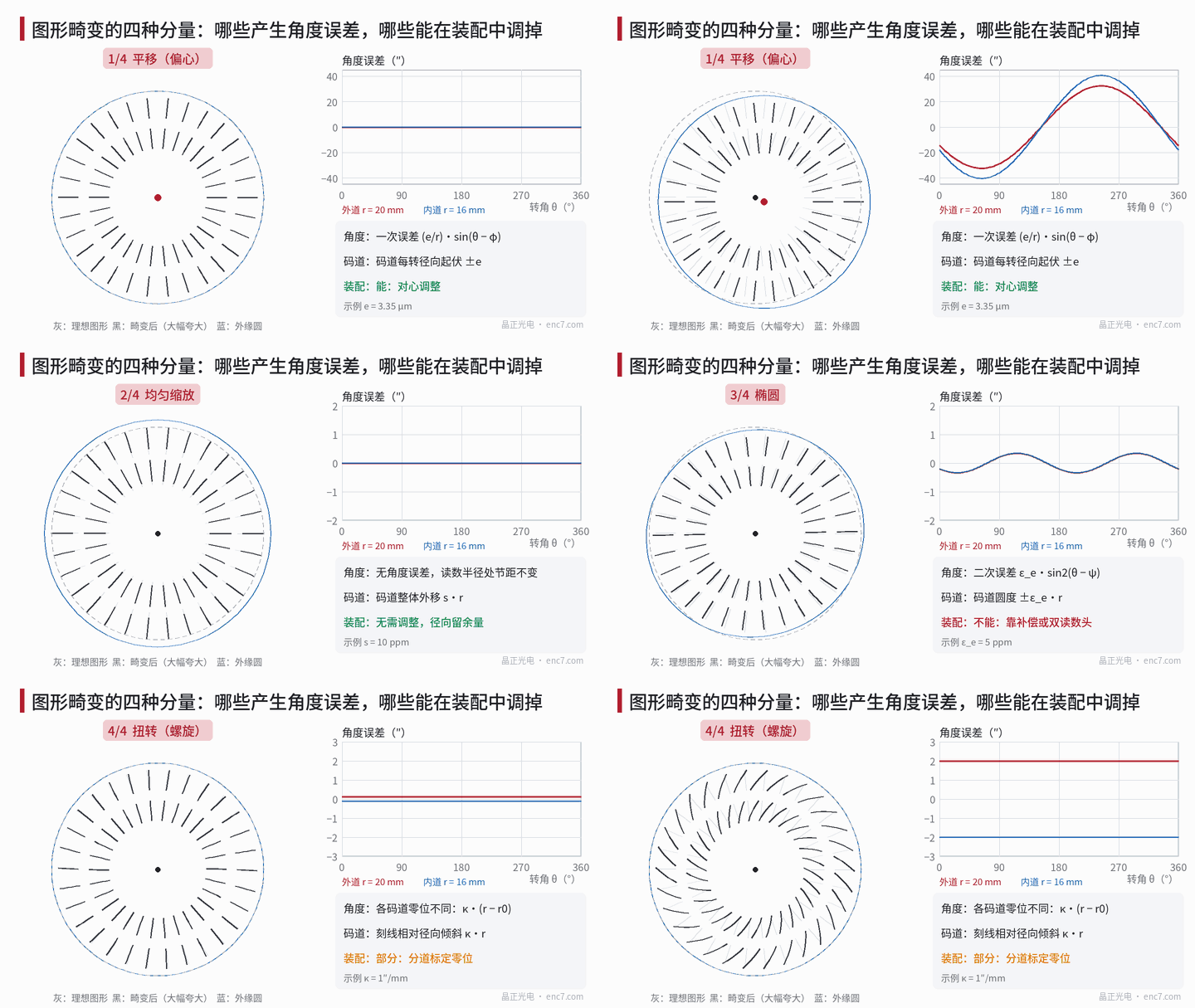
Definition of the components: tangential and radial displacement
Let a point on the pattern have ideal polar coordinates (r, θ), and after distortion a tangential displacement u_t and a radial displacement u_r. For small deformations the overall pattern distortion can be written
u_t = −t_x·sinθ + t_y·cosθ + r·[ω + κ·(r − r0) − E_c·sin2θ + E_s·cos2θ]
u_r = t_x·cosθ + t_y·sinθ + r·[s + E_c·cos2θ + E_s·sin2θ]
Meaning of the parameters: (t_x, t_y) is translation, with eccentricity e = √(t_x² + t_y²); ω is a rigid rotation; κ is the twist rate, that is the change of rotation angle with radius; s is uniform scaling; E_c and E_s are the two components of the deviatoric strain, and the ellipticity ε_e = √(E_c² + E_s²) equals half the difference of the two principal strains. The angle error at read radius r is Δθ = u_t / r; the change in the radial position of a track is u_r. Higher-order k-fold symmetric deformations add a k-th harmonic to each equation and are not expanded here (for the relation between affine deformation and harmonic order, see the article on sources of graduation error in this library).
What each component affects
| Component | Angle error at the read radius | Radial track position | Signal |
|---|---|---|---|
| Translation e | First harmonic: (e/r)·sin(θ − φ) | Rise and fall of ±e once per revolution | Amplitude varies once per revolution |
| Rotation ω | A constant, i.e. an index offset | Unchanged | None |
| Uniform scaling s | None | Overall outward shift s·r | None (pitch unchanged) |
| Ellipse ε_e | Second harmonic: ε_e·sin2(θ − ψ) | Roundness ±ε_e·r | Essentially none |
| Twist κ | Index of each track differs by κ·Δr | Unchanged | Lines depart from the radial direction by κ·r |
Quantitatively, with the example parameters (outer track r = 20 mm, inner track r = 16 mm):
- Translation of 3.35 μm: first-harmonic error 34.6″ on the outer track and 43.2″ on the inner track, larger at smaller radius.
- Uniform scaling of 10 ppm: overall outward shift of 0.2 μm on the outer track, and zero angle error. The pitch of radial graduation lines at a fixed read radius is 2πr/N, independent of scaling, so scaling changes neither the angle nor the pitch match. It only affects the radial alignment of the track with the reading window. A 1 K temperature difference already scales soda-lime glass by about 9 ppm, so 10 ppm is in any case hard to isolate on its own in engineering practice.
- Ellipse of 5 ppm: a second-harmonic error of 1.03″ on both tracks, independent of radius; track roundness is only ±0.1 μm. Trading ±0.1 μm of roundness for about 1″ of error is where ellipse is sensitive. The converse does not hold: a two-lobe deformation that is purely radial, with no tangential component (for example a press fit that pinches the track into two lobes), also worsens roundness but produces no angle error, so track roundness cannot be used to infer the second-harmonic error.
- Twist of 1″/mm (about r0 = 18 mm): index +2″ on the outer track and −2″ on the inner track, a difference of 4″ between the two tracks. The inclination of the lines relative to the radial direction, κ·r, is about 0.1 mrad; with a detection window 1 mm high radially and a pitch of 50 μm the amplitude loss is negligible. Twist often comes from a slow drift of the angular reference during writing: when rings are written sequentially, different radii are written at different times. It is almost harmless for a single-track incremental encoder, but it produces error directly in the synchronisation of an absolute track with the incremental track, and in the phase relation between the index track and the incremental track.
Least-squares decomposition from measured coordinates
The two equations above are linear in the seven parameters (t_x, t_y, ω, κ, s, E_c, E_s); once u_t and u_r have been measured at enough points, the parameters can be solved in a single step. One measurement point must be kept in mind: a radial graduation line yields only a tangential position — its radial coordinate is chosen by the measurer; radial information can come only from circular features such as the centring ring or the inner and outer edges of a track.
Worked example (simulated data): a vision measuring machine measures the tangential deviation of the centres of 72 graduation lines at each of r = 16 mm and 20 mm (repeatability 0.1 μm), and the radial deviation at 72 points on the outer track edge at r = 21 mm (repeatability 0.15 μm). The weighted least-squares result is shown in Figure 2:
| Parameter | Set value | Fitted value ± standard uncertainty |
|---|---|---|
| t_x / t_y (μm) | 3.00 / −1.50 | 3.00 / −1.51, ± 0.01 |
| Rotation ω (″) | 20.00 | 20.02 ± 0.10 |
| Twist κ (″/mm) | 1.00 | 0.98 ± 0.05 |
| Scaling s (ppm) | 10.00 | 9.66 ± 0.84 |
| E_c / E_s (ppm) | 4.00 / −3.00 | 3.85 / −2.81, ± 0.57 |
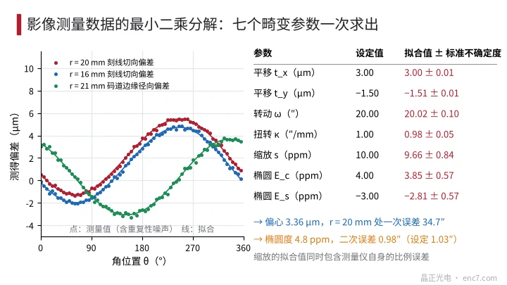
Three conclusions follow. First, translation and twist are obtained very accurately from coordinate measurement: the uncertainty on an eccentricity of 3.36 μm is only of order 0.01 μm. Second, the fitted ellipticity is 4.8 ppm (0.98″) with an uncertainty of about ±0.12″: a single-point repeatability of 0.1 μm is already tight for a sub-arcsecond second-harmonic error, and the second-harmonic component is better measured by calibrating a readhead against an angle reference. Third, the fitted value of s is mixed with the vision measuring machine’s own scale error and with temperature, so it has little meaning on its own. Observability must also be watched: if angle is measured at only one radius, κ cannot be separated from ω and s is invisible; if E_c and E_s fitted separately from the tangential and from the radial data disagree, the deformation is not a uniform affine deformation.
Which terms can be trimmed out during assembly
- Translation: yes. Centring puts the pattern centre on the axis of rotation; the residual is set by the centring method. Eccentricity of the disc pattern relative to the bore can be relaxed to within the centring capability.
- Rotation: yes. It is only the index and is calibrated electrically.
- Uniform scaling: no adjustment is needed, but the track width should leave margin for radial alignment, especially on narrow tracks and absolute tracks.
- Ellipse: cannot be trimmed out by centring. After averaging a pair of diametrically opposed readheads the second-harmonic term remains unchanged; two readheads 90° apart, or a compensation table, are required. If the ellipse comes from bonding or clamping stress, the assembly method should be changed rather than the pattern blamed.
- Twist: partly. Mounting the readhead at the nominal radius avoids the extra offset κ·Δr; the index difference between tracks is calibrated track by track.
Engineering points
- Write acceptance limits for pattern deviation by component: separate limits for eccentricity, ellipticity and twist rate, not a single “maximum position deviation”.
- The measurement scheme must include the tangential positions of graduation lines at two radii and the radial positions of circular features, otherwise twist and scaling cannot be separated.
- When the second-harmonic error is required at the 1″ level, track roundness is only of order ±0.1 μm and vision measurement cannot resolve it; verify instead by angle calibration.
- Scaling of 10 ppm produces no angle error, and a 1 K temperature difference already scales soda-lime glass by about 9 ppm, so scaling need not be treated as an accuracy specification.
- Where an absolute track or index-track synchronisation is required, specify the twist rate or the angular deviation between tracks separately: for example, two tracks 4 mm apart and a requirement of ±2″ imply κ ≤ 0.5″/mm.
Summary
Viewed by component, pattern distortions differ greatly in their effect: translation becomes a first-harmonic error and can be centred out; uniform scaling does not change the angle; ellipse becomes a second-harmonic error that cannot be removed by centring; twist changes the index relation between tracks. Least-squares fitting of tangential coordinates at two radii plus radial coordinates of circular features separates these components so that each can be accepted on its own.
Translated from the ENC7 Chinese technical library (article 0274). Read the Chinese original. Need a disc built to your drawing? Request a quote or see our custom encoder discs.
© Langfang Jingzheng Optoelectronic Technology Co., Ltd. All rights reserved. This article was created with AI assistance.