Manufacturing
Photoresist Coating: Why the Glass Is Spun

Photoresist has to be applied as a thin, even film, and the most common method is spin coating: resist is dispensed at the centre, the substrate spins at high speed and the excess is flung off. This article covers the four stages of spin coating, how film thickness relates to spin speed, common problems such as edge bead, and why the coated plate still needs a soft bake.
Once the glass has been chrome-coated, the next step is to cover it with a layer of photoresist. This layer is usually only of the order of a micron, and it must be equally thick over the whole plate: where the resist is thicker and where it is thinner, exposure and development behave differently, and in the end the line width differs too. Neither a brush nor a roller can achieve that evenness; the answer is to spin the glass.

The four stages of spin coating
As shown in Figure 1, one spin-coating cycle has roughly four steps:
- Dispense: the substrate is held by a vacuum chuck and a set amount of resist is dispensed at the centre.
- Low-speed spreading: the substrate turns slowly, the resist spreads outwards and covers the whole surface.
- High-speed spin-off: the substrate accelerates to the set speed, centrifugal force throws most of the resist off the edge, and the film thins rapidly.
- Evaporation and setting: solvent keeps evaporating, the resist grows more and more viscous until it can no longer flow, and the thickness is essentially fixed.
The resist that finally stays on the substrate is often only a small fraction of the puddle that was dispensed; the rest is flung off.
How film thickness relates to spin speed
Every point of the film is acted on by two forces: centrifugal force pulls the resist outwards, and its viscosity holds it back. The faster the spin, the stronger the outward pull and the thinner the film; the more viscous the resist, the better it holds and the thicker the film. Add the gradual “freezing” caused by solvent evaporation, and experience gives a simple relation:
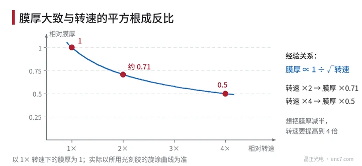
Film thickness is roughly inversely proportional to the square root of spin speed.
This allows a quick estimate: doubling the speed (2×) gives about 1 ÷ √2 ≈ 71% of the original thickness; only quadrupling it (4×) halves the thickness (see Figure 2). So to change thickness substantially, adjusting speed alone is not enough; usually a resist of different viscosity is used. In production every resist has its own speed–thickness curve, and measured values are what count.
Why spinning makes it even
Spin coating has a neat “self-levelling” effect: where the resist layer is thicker it flows outwards faster and thins faster; where it is thin it flows slowly. Thick regions therefore chase thin ones down, and the whole film tends towards uniformity by itself. As long as the substrate is seated straight and the speed is stable, the thickness over most of the central area can be made very uniform.
The main factors affecting uniformity are:
- whether the resist volume and dispense position are consistent, and whether the resist contains bubbles;
- whether acceleration and spin speed are repeatable;
- airflow, temperature and humidity in the bowl, which determine how fast the solvent evaporates;
- whether the substrate is clean and dry.
Edge bead and other defects
Because of surface tension, the resist at the substrate edge bulges into a rim (the “edge bead”) thicker than the centre; on square substrates it is more pronounced at the four corners – see the cross-section in Figure 1. The usual remedies are to keep the pattern area away from the edge, or to rinse off the resist around the edge with solvent.
Two other typical defects: comets, where a particle on the substrate drags a tail behind it as the resist flows past; and striations (radial streaks), which are related to uneven solvent evaporation. Both make the local film thickness different and finally show up as uneven line width or residual chrome.
Why a soft bake after coating
Freshly coated resist still contains solvent and is soft and tacky. The soft bake heats it for a while to drive off most of the solvent, which does three things:
- the film hardens and will not stick to the photomask during exposure;
- resist and chrome film bond more firmly, so the resist is less likely to lift during development;
- the subsequent exposure and development conditions become stable.
The soft bake must be moderate too. If the temperature is too low or the time too short, much solvent remains and even unexposed resist is partly dissolved during development; if it is overbaked, the photosensitive component in the resist decomposes and sensitivity drops. Uniform heating of the whole plate matters just as much.
Summary
Spin coating relies on the balance between centrifugal force and viscosity, plus solvent evaporation, to spread resist into a thin, uniform layer. Film thickness is roughly inversely proportional to the square root of spin speed, a margin must be left at the edge and particles must be strictly controlled. The soft bake sets the film and prepares it for the next step, exposure.
Translated from the ENC7 Chinese technical library (article 0023). Read the Chinese original. Need a disc built to your drawing? Request a quote or see our custom encoder discs.
© Langfang Jingzheng Optoelectronic Technology Co., Ltd. All rights reserved. This article was created with AI assistance.