Glass & substrate science
Poorly Annealed Glass: Residual Stress, Birefringence, Polarimetry

Cooling too fast freezes the temperature difference inside a plate into residual stress. Using a viscoelastic model and a freezing estimate, this article relates stress to cooling rate and plate thickness, explains why polarimetric measurement must look through the plate edge to see through-thickness stress, and estimates the 2nd-order angular error of a cut disc, warp of small pieces and the risk of cracking.
The incoming-material specification says “internal stress ≤ 10 nm/cm”, yet after cutting into disc blanks the dimensions have drifted by a few ppm, or small pieces do not lie flat on the table. The root cause of such problems lies in how the glass was cooled before it left the glass works: if the glass has already stiffened while a temperature difference exists inside the plate, that temperature difference stays locked into the structure. This article first calculates how the stress is frozen in, then explains why polarimetric measurement often fails to see it, and finally estimates how much of it is released on cutting.
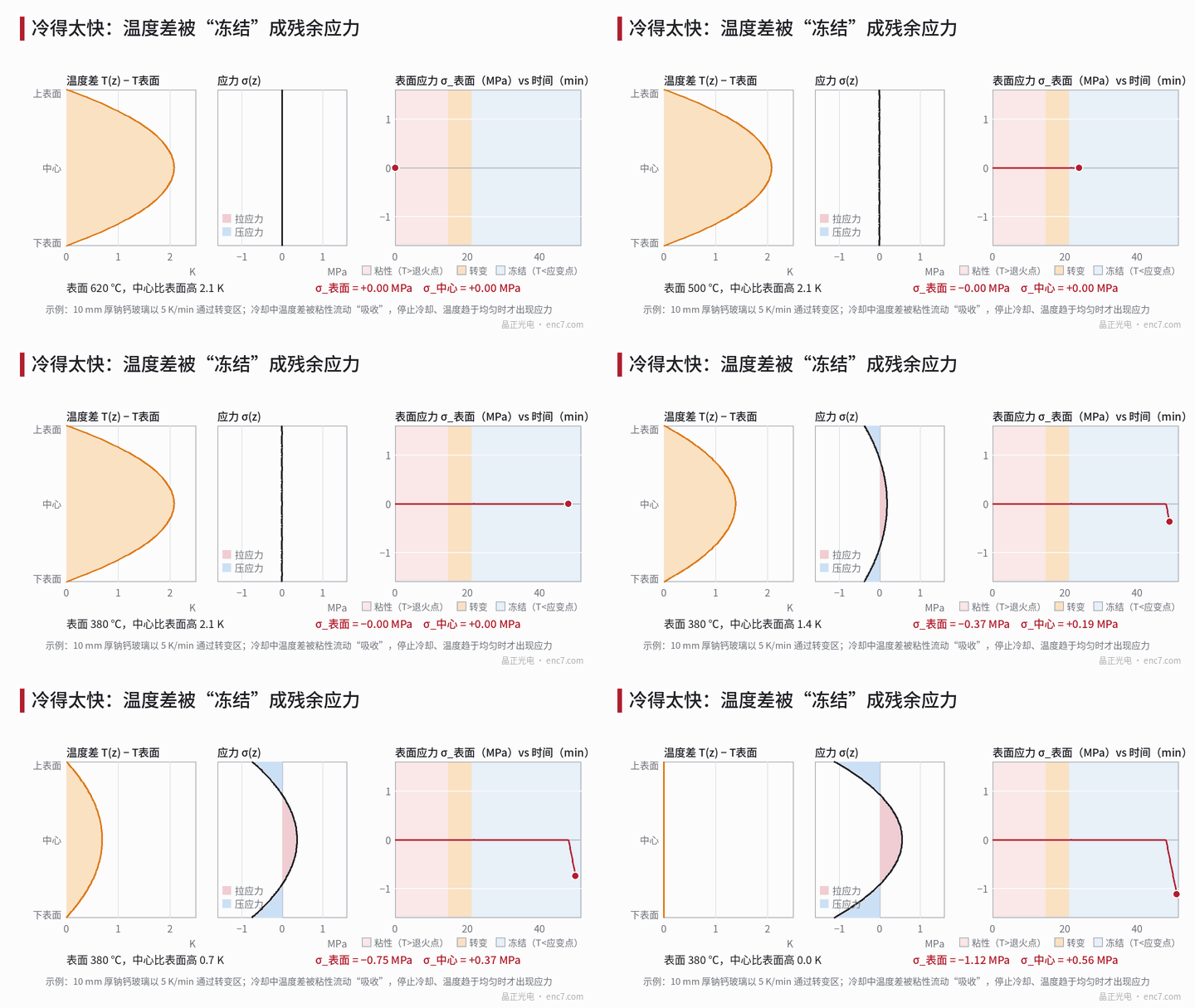
Where residual stress comes from: a frozen temperature difference
When a flat plate of thickness 2a is cooled at a constant rate h, a parabolic temperature profile forms through the plate, with the centre hotter than the surface by
ΔT = h·a² / (2κ)
where κ is the thermal diffusivity, about 5×10⁻⁷ m²/s for soda-lime glass (example value). Above the annealing point the relaxation time of the glass is no more than a few tens of seconds (see the viscosity-curve article in this library), so any stress caused by the temperature difference is immediately wiped out by viscous flow; when the glass stiffens on passing through the transformation range, this temperature difference is frozen in. As the temperature then becomes uniform, the centre shrinks more than the surface by the amount corresponding to ΔT, and the surface is pulled into compression:
σ_surface = −(2/3)·E·α·ΔT/(1−ν), σ_centre = +(1/3)·E·α·ΔT/(1−ν)
With E = 70 GPa, α = 9×10⁻⁶/K and ν = 0.22, E·α/(1−ν) ≈ 0.81 MPa/K. Integrating the case in Figure 1 with a layer-by-layer Maxwell model (τ = η/G, η from the VFT fit for soda-lime glass) gives −1.12 MPa at the surface and +0.56 MPa in the centre, in agreement with the formula above.
The stress is proportional to the cooling rate and to the square of the plate thickness. Converted with the stress-optical coefficient of soda-lime glass, C ≈ 27 nm/cm/MPa (10 nm/cm corresponds to about 0.37 MPa), the edge-view readings at the surface (nm/cm) are:
| Plate thickness | 1 K/min | 5 K/min | 20 K/min |
|---|---|---|---|
| 2 mm | 0.2 | 1.2 | 4.8 |
| 10 mm | 6 | 30 | 121 |
| 20 mm | 24 | 121 | 485 |
To keep the reading down to 10 nm/cm (about 0.37 MPa at the surface, corresponding to a frozen temperature difference ΔT ≤ 0.69 K), the permissible cooling rate is h ≤ 2κΔT/a²: about 41 K/min for 2 mm, about 1.6 K/min for 10 mm and about 0.41 K/min for 20 mm thickness. Thick plates must be cooled slowly because the permissible rate falls with the square of the thickness. Annealing also requires a hold near the annealing point so that the temperature equalises and old stress relaxes: the hold time should exceed the through-thickness diffusion time a²/κ (about 50 s for a = 5 mm). Only the region around the transformation range really needs slow cooling; below the strain point the rate can be increased, limited only by transient thermal stress, which disappears once the whole plate is at a uniform temperature.
Photoelastic measurement: which direction to look
The photoelastic relation is σ₁ − σ₂ = Δ/(C·t), where Δ is the optical path difference (see the material-specification article in this library for details). The key point is that it responds only to the difference between the two principal stresses perpendicular to the light path. Residual stress through the thickness of a flat plate satisfies σ_x = σ_y = σ(z), σ_z = 0. With light at normal incidence to the plate surface one sees σ_x − σ_y = 0: the reading is zero and nothing is visible. Looking through the plate edge, parallel to the plate surface, one sees σ_y − σ_z = σ(z), and the optical path difference is Δ(z) = C·σ(z)·L, where L is the optical path length. A 10 mm plate cooled at 5 K/min shows about 30 nm/cm at the surface, i.e. about 300 nm over a 100 mm wide light path, while the normal-incidence reading is zero. At normal incidence one sees only in-plane non-uniformity (σ_r ≠ σ_θ, caused by the plate edge and the centre cooling differently).
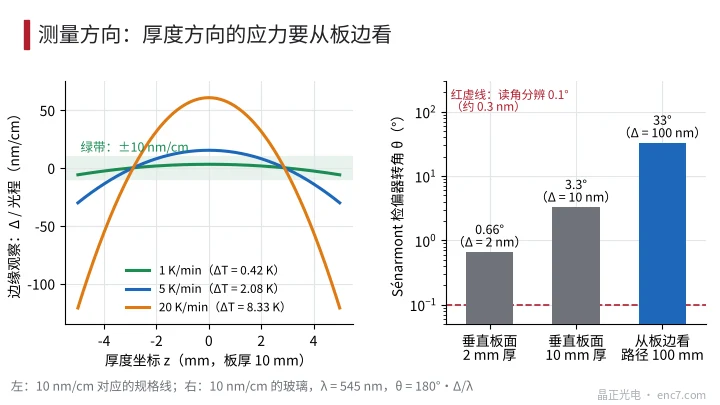
For quantitative work the Sénarmont method is used: polariser, specimen (principal axes at 45° to the polarisation direction), λ/4 plate and analyser; the analyser is rotated to extinction, and the optical path difference is
Δ = λ·θ / 180° (θ is the analyser rotation in degrees)
At λ = 545 nm this is about 3.0 nm per degree. For soda-lime glass at 10 nm/cm, a 2 mm thick piece at normal incidence gives only 2 nm, an angle of 0.66°; 10 mm thickness gives 3.3°; viewed through the edge over a 100 mm path it is 33°. If the angle can be read to 0.1° (about 0.3 nm), the resolution on a 2 mm thick piece is only about 1.5 nm/cm, so thin pieces need an automatic polarimeter. Optical-glass manufacturers’ data typically specify precision annealing as ≤ 10 nm/cm, with special annealing down to 6 or 4 nm/cm; ISO 10110-2 can call for less than 2 nm/cm for optics used in polarisation instruments.
What happens after cutting
Disc ovality. When the in-plane principal stress difference σ₁ − σ₂ is released, the strain difference between the two directions is (1+ν)(σ₁ − σ₂)/E. The disc becomes elliptical, producing a 2nd-harmonic angular error with an amplitude of about half the strain difference:
Δθ₂ ≈ (1+ν)(σ₁ − σ₂) / (2E)
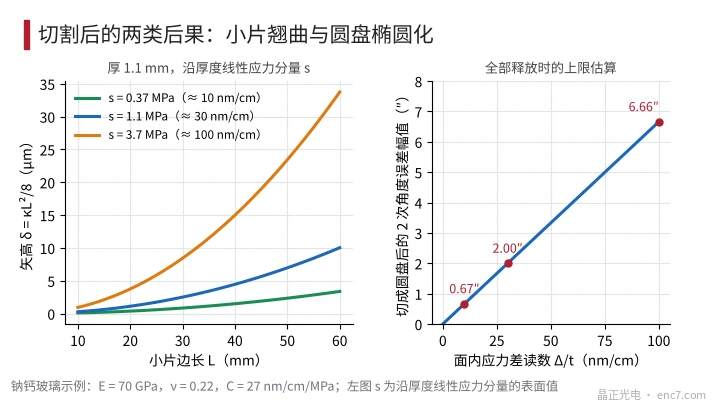
10 nm/cm (0.37 MPa) corresponds to a strain difference of about 6.5 ppm, Δθ₂ ≈ 3.2 μrad ≈ 0.67″; at 100 nm/cm it is about 6.7″. This is the upper limit for complete release. The equibiaxial part only scales the radius and does not change angles; at r = 20 mm it amounts to about 0.22 μm per MPa.
Warp of small pieces. A linear stress component that is asymmetric through the thickness (surface value s) gives the plate a curvature κ = 2s(1−ν)/(E·t). A free plate already carries this curvature; small pieces cut from a plate that was held flat by vacuum or bonding, or that had material removed by single-side grinding and polishing, will recover or change it. For 1.1 mm thickness and s = 0.37 MPa, R ≈ 133 m; the sagitta of a 20 mm piece is δ = κL²/8 ≈ 0.37 μm, and about 2.3 μm for 50 mm; with s = 3.7 MPa (about 100 nm/cm) the values are 3.7 μm and 23 μm respectively (Figure 3).
Cracking. For a 50 μm edge flaw, K ≈ 1.12σ√(πa), about 0.014 MPa·√m per MPa, so reaching a fracture toughness of 0.75 MPa·√m requires a tensile stress of about 53 MPa. Insufficient annealing at a few tens to a few hundred nm/cm will not cause spontaneous cracking; the real danger is quench stress of several tens of MPa, and such glass can crack further during cutting.
Engineering notes
- The incoming-material specification should state the measurement direction and position: a reading at normal incidence reflects only the in-plane stress difference; through-thickness residual stress must be measured through the plate edge.
- The permissible cooling rate of thick plates is inversely proportional to the square of the thickness; for ≤ 10 nm/cm a 10 mm plate needs about 1.6 K/min. Do not use the annealing schedule of thin plates for thick plates.
- At normal incidence the optical path difference of thin pieces is only a few nm; use an automatic polarimeter with a resolution of the order of 0.1 nm.
- Decide between cutting before coating and coating before cutting with the 2nd-order error estimate in mind: a disc cut from 100 nm/cm material can have a 2nd-order angular error of several arcseconds.
- Single-side grinding/polishing and single-side coating break the stress symmetry; estimate the curvature in advance and process both sides symmetrically if necessary.
- For a batch suspected of excessive stress, first do an edge-view check and a trial cut and see whether dimensions and flatness change, then decide whether to re-anneal.
Summary
Residual stress is a temperature difference frozen in during cooling: compression at the surface, tension in the centre, proportional to the cooling rate and to the square of the plate thickness; bringing a 10 mm soda-lime plate down to 10 nm/cm requires about 1.6 K/min. Through-thickness stress is invisible at normal incidence and must be viewed through the plate edge. On cutting, the in-plane stress difference is released as a 2nd-order angular error and the asymmetric component warps small pieces; the magnitudes can be estimated with the formulas in this article.
Translated from the ENC7 Chinese technical library (article 0563). Read the Chinese original. Need a disc built to your drawing? Request a quote or see our custom encoder discs.
© Langfang Jingzheng Optoelectronic Technology Co., Ltd. All rights reserved. This article was created with AI assistance.