Industry applications in depth
Powered surgical instruments: motor encoders under 8 mm OD and steam sterilization
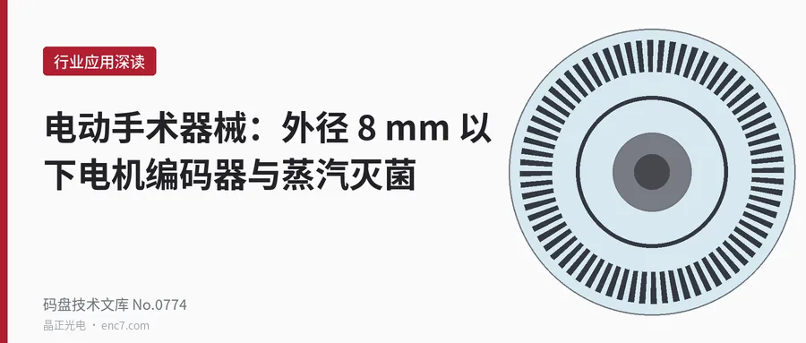
A Ø6 mm encoder disc has a circumference of only 15.7 mm at r = 2.5 mm, so the upper limit on line count is about 750–1060 lines, and 2 μm of eccentricity is already 165″. This article then calculates, for a 134 ℃ steam-sterilization cycle, the expansion mismatch and adhesive-layer strain of glass, stainless-steel and polyimide substrates against the hub, and gives the main points of sealing and selection.
The motors of hand-held powered surgical instruments often have an outside diameter below 8 mm, run at high speed, and must also survive several hundred cycles of high-pressure steam sterilization at 134 ℃. The encoder disc that fits inside is only about Ø6 mm: the geometry forces both the line count and the read radius to very small values, and every sterilization temperature-and-humidity cycle pulls the substrate, the hub and the adhesive layer once more. This article calculates the problem in three steps: the geometric limits on line count and eccentricity, the thermal mismatch and adhesive-layer strain of the substrate in the sterilization cycle, and the sealing requirements against steam and condensation. The figures are examples.
A small encoder disc: the upper limit on line count, and eccentricity
At a read radius r = 2.5 mm the circumference of one revolution is 2πr = 15.71 mm, and the pitch is p = 2πr/N:
| Line count N | Pitch p | Gap allowed by near-field imaging, p²/(5λ) |
|---|---|---|
| 500 | 31.4 μm | about 224 μm |
| 1000 | 15.7 μm | about 56 μm |
| 2000 | 7.85 μm | about 14 μm |
The gap column takes one fifth of p²/λ as a margin (λ = 0.88 μm; the margin is an assumption). In a miniature motor the gap between the readhead and the disc is fixed by the structure and is generally difficult to hold within a few tens of micrometres, so the practical upper limit on line count is set by the gap:
N_max = 2πr / √(5·g·λ)
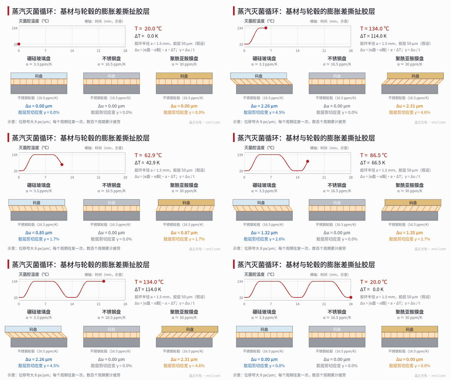
At g = 100 μm this is about 750 lines, and at g = 50 μm about 1060 lines (Figure 2, left); a still finer pitch is not realistic given the gap and the adjustment. Higher angular resolution has to be obtained by sine-cosine interpolation. At high speed the frequency must also be checked: at 500 lines and 4 × ten-thousand r/min the A/B frequency is 333 kHz. Centrifugal stress is not a constraint: for a glass disc of Ø6/Ø3 the hoop stress at the bore is only about 1.3 MPa at 8 × ten-thousand r/min.
The cost of a small radius is that eccentricity is amplified. The first-order error is Δθ = e/r; at r = 2.5 mm each micrometre of eccentricity is 82.5″, and 2 μm is already 165″. The same 2 μm at r = 20 mm is only 20.6″, see Figure 2, right. The eccentricity of a small disc is determined mainly by the fit and the bonding of the disc to the hub, and the sterilization cycle discussed below acts directly on this term.
Temperature and humidity load of the sterilization cycle
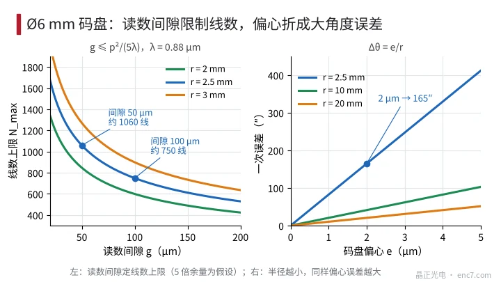
The pressure of saturated steam at 134 ℃ is about 3 bar (absolute). The temperature is held for a few minutes, then a vacuum is drawn for drying. Each cycle takes the parts from 20 ℃ to 134 ℃, so ΔT = 114 K, while they are also in a humidity close to saturation.
The encoder disc is usually bonded to the flange face of the hub. If the coefficients of thermal expansion of the substrate and the hub differ, the radial mismatch at the adhesive ring is
Δu = |α_disc − α_hub|·a·ΔT
where a is the mean radius of the adhesive ring, taken as 1.5 mm. In a face bond the mismatch appears as shear in the adhesive layer, and the amplitude of the shear strain is
γ = Δu / t
where t is the adhesive thickness, taken as 50 μm. With a stainless-steel hub (16.5×10⁻⁶/K):
| Substrate | α (×10⁻⁶/K) | Δu | γ (50 μm) | Other risks |
|---|---|---|---|---|
| Borosilicate glass | 3.3 | 2.26 μm | 4.5% | Brittle, chipping and shock; fine graduation |
| Soda-lime glass | 9 | 1.28 μm | 2.6% | Greater risk of sodium leaching in heat and moisture |
| Stainless steel (same grade as the hub) | 16.5 | about 0 | about 0 | Fine-pitch patterns are difficult; mostly reflective |
| Polyimide film | about 20–40 (taken as 30) | 2.31 μm | 4.6% | Hygroscopic expansion, of the order of 0.1–0.3% |
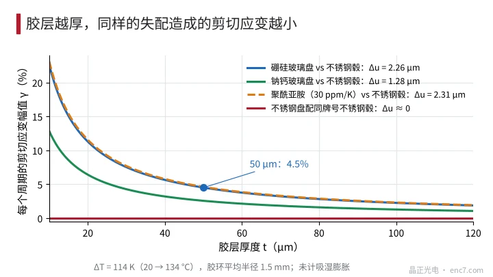
After a polyimide absorbs moisture there is a further linear expansion, of the same order as the thermal mismatch; the exact figure depends on the grade and must be measured. Figure 3 shows the effect of adhesive thickness: increasing the thickness from 50 μm to 100 μm halves the strain; but a thicker layer creeps more at high temperature, and the axial position of the disc is also less stable.
A shear strain of 4.5% is applied back and forth in every cycle, so after several hundred cycles it is a fatigue problem: the failure strain of a rigid adhesive is generally only a few per cent, and 134 ℃ is often already close to or above its glass-transition temperature, so the modulus drops sharply and creep displacement accumulates from cycle to cycle. The mismatch finally appears as an asymmetric slip of the disc relative to the hub, of the same order as Δu; 2 μm of slip at r = 2.5 mm is an eccentricity error of 165″.
Steam, pressure difference and condensation
When the air in a sealed cavity is heated to 134 ℃ the pressure rises to about 1.4 bar (absolute); outside there is steam at about 3 bar, so a pressure difference of about 1.6 bar drives steam into the cavity. During vacuum drying the difference is reversed and pushes outward. Elastomers, plastic housings and adhesive joints all permit some moisture permeation, and each cycle is equivalent to one “breath” of the cavity.
Moisture that has entered condenses on cool-down. Suppose the cavity volume is 0.5 cm³ and the partial pressure of water vapour after ingress is 30 kPa (equivalent to saturated steam at about 69 ℃, an assumption). After cooling to room temperature almost all of it condenses, about 0.08 mg, which spread over a Ø6 disc would be a water film about 3 μm thick. In reality it forms droplets, which scatter 880 nm light severely and appear as a sudden drop in signal amplitude.
Engineering points
- First set the upper limit on line count from the read gap: N_max = 2πr/√(5gλ). For a Ø6 mm disc, about 500 lines is the more robust choice, and higher resolution is obtained by interpolation.
- At a small radius the angular error of eccentricity is amplified: 2 μm is already 165″. Fit and bonding must be controlled at the micrometre level.
- Prefer a substrate whose coefficient of expansion is close to that of the hub: a stainless-steel disc on a hub of the same grade has almost no mismatch; for glass and polyimide, calculate γ = Δu/t and verify it over cycles.
- Choose an adhesive grade that withstands 134 ℃ steam and whose glass-transition temperature is above the sterilization temperature; mechanical clamping or laser welding can also replace a full-circle bond.
- Prefer a hermetic construction for the seal (glass sealing, a laser-welded housing). If an elastomer is used, choose a steam-resistant grade and calculate the life from compression set.
- Verify over the actual number of cycles: measure signal amplitude, zero drift and the internal dew point every so many cycles, rather than looking only at a single pass.
In brief
The upper limit on the line count of a Ø6 mm encoder disc is set jointly by the read gap and the radius, at about 750–1060 lines, and 2 μm of eccentricity already reaches 165″. In the sterilization cycle a temperature difference of 114 K produces a mismatch of about 2 μm between glass or polyimide and a stainless-steel hub, and a shear strain of about 4.5% in the adhesive layer; after several hundred cycles this becomes the main risk of eccentricity and debonding. Choosing a substrate whose expansion matches the hub, controlling the adhesive layer and using a hermetic construction is the more robust route.
Translated from the ENC7 Chinese technical library (article 0774). Read the Chinese original. Need a disc built to your drawing? Request a quote or see our custom encoder discs.
© Langfang Jingzheng Optoelectronic Technology Co., Ltd. All rights reserved. This article was created with AI assistance.