Selection
PPR, CPR and LPR: Conversion Pitfalls Between Line Count, Pulses and Counts
LPR is line count; PPR often equals line count but may already include interpolation; CPR may be x4 counts or may be cycles; and interpolation factor is written two ways. Using the conversion chain line count → signal periods → PPR → CPR and three frequencies, this article works out what happens to pitch, bandwidth and receiver frequency when one step is misread, and gives a recommended way of writing specifications.
The RFQ says “10000”. The disc maker quotes on line count, the readhead maker picks a chip on x4 counts, the drive maker sets a divider on pulses. None of the three has miscalculated, yet together they are out by 4× or even 16×. Line count, pulse count and count have no unified definition across documentation; the factor hidden behind the unit “P/R” is what matters. This article writes each step from disc line count to controller count as a multiplying factor and works out the consequences of each misreading.
Definitions: what each abbreviation means
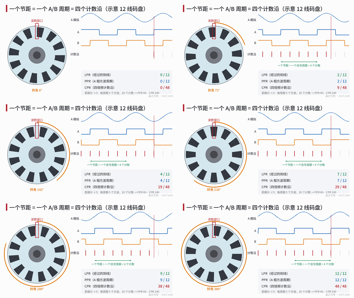
- LPR (lines per revolution): the number of line periods per revolution on the incremental track, i.e. line count N. One dark line plus one clear gap counts as one period.
- PPR (pulses per revolution): usually the number of square-wave cycles output per revolution per channel (e.g. phase A). Without interpolation and with imaging readout, PPR = N; with interpolation, PPR = k·N. A few documents also call the x4-decoded count PPR.
- CPR: in most documents, counts per revolution, i.e. 4·PPR after x4 decoding; some use it for cycles per revolution, i.e. signal periods per revolution.
So PPR “often equals” LPR and CPR “often equals” 4× LPR, but neither “often” can be dropped.
The conversion chain: one factor per step
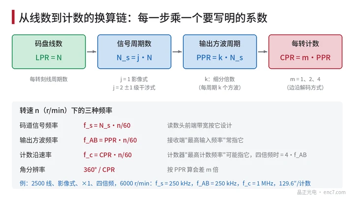
LPR = N → signal periods N_s = j·N → PPR = k·N_s → CPR = m·PPR
where:
- j: readout method. Imaging (including Talbot imaging) gives one signal period per pitch, j = 1; ±1-order interferential readout gives a signal period half the pitch, j = 2. A disc at r = 20 mm with 8 μm pitch has about 15,708 lines; with an interferential readhead it gives about 31,416 signal periods per revolution. If the user asks for “31,416 PPR”, the disc only needs 15,708 lines; drawn directly as 31,416 lines from the PPR, the pitch would be only 4 μm.
- k: interpolation factor — k square-wave cycles output per signal period.
- m: decoding — single-edge counting m = 1, both edges of A m = 2, all four edges of A and B m = 4.
Angular resolution = 360°/CPR. For 2,500 lines, imaging readout, no interpolation and x4 decoding, CPR = 10,000 and each count is 129.6″; wrongly using PPR = 2,500 gives 518.4″, out by 4×.
Two notations for interpolation factor
“Interpolation” also has two conventions:
- ×k: k A/B square-wave cycles per signal period, 4k counts per period after x4;
- k counts/period: k counts per signal period, equivalent to k/4 square-wave cycles.
The two differ by 4×. “2,048 lines × 1,024 interpolation” in the counts convention is 2,097,152 counts/rev (21 bits); read as 1,024 square-wave cycles per period, it becomes 8,388,608 (23 bits) after x4, with 4× higher output frequency. When an absolute encoder is specified in bits b, there are 2^b counts per revolution, and the ratio to N_s is counts per period — reading it in the counts convention is least error-prone.
Three frequencies: which one bandwidth design uses
At speed n (r/min) there are three frequencies:
- Track signal frequency f_s = N_s·n/60 — the readhead front end (photodiodes, transimpedance amplifier, comparator) is designed for this bandwidth;
- Output square-wave frequency f_AB = PPR·n/60 — a receiver’s “maximum input frequency” usually refers to this;
- Counting-edge rate f_c = CPR·n/60 — a counter’s “maximum count frequency” may refer to this; with x4 it is 4·f_AB.
When a receiver spec only says “maximum frequency 5 MHz”, you must ask whether it is square-wave frequency or counting-edge rate. With x4 decoding, the nominal interval between adjacent counting edges is 1/(4·f_AB); when A/B phase deviates from 90° by φ, the minimum interval shrinks to (90° − φ)/(360°·f_AB). At f_AB = 1.25 MHz the nominal is 200 ns, but at φ = 20° only about 156 ns remains; check the receiver’s minimum edge separation against the latter.
Consequences of one wrong step
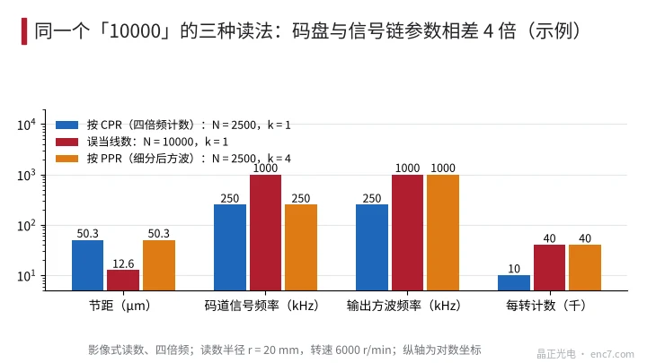
Taking “10000” as the example, read radius 20 mm, 6,000 r/min, imaging readout, x4 decoding (Figure 3):
| Interpretation | Line count N | Pitch | Track signal frequency | Square-wave frequency | Counts per rev |
|---|---|---|---|---|---|
| CPR (x4 counts) | 2,500 | 50.3 μm | 250 kHz | 250 kHz | 10,000 |
| Mistaken for line count | 10,000 | 12.6 μm | 1 MHz | 1 MHz | 40,000 |
| PPR (including ×4 interpolation) | 2,500 | 50.3 μm | 250 kHz | 1 MHz | 40,000 |
The second row is a disc-side error: pitch shrinks to a quarter, the gap window of an imaging readhead shrinks with it (see the library article on drawing specification errors), and front-end bandwidth must rise 4×, so photodiode capacitance and transimpedance amplifier margins must all be recalculated. The third row is a signal-chain error: the disc is unchanged, but the interpolator’s output frequency and counting-edge rate are 4× higher and the receiver may lose counts at high speed.
When the interpolation convention is wrong the consequences are more hidden. 2,500 lines requiring 100,000 counts per revolution should be 40 counts per period, i.e. ×10; if set to ×40, at 3,000 r/min the square-wave frequency goes from 1.25 MHz to 5 MHz and the counting-edge rate from 5 MHz to 20 MHz. Everything is fine during low-speed commissioning; problems only appear at high speed.
Recommended way to write it
On RFQs and drawings, write four numbers and three conditions separately:
- Disc line count N (line periods per revolution), appearing only on the disc drawing;
- Readout method and signal periods per revolution N_s;
- Interpolation factor, written as “k square-wave cycles (4k counts) per signal period”;
- Counts per revolution CPR, stating the decoding method;
- Conditions: maximum speed, and the receiver’s maximum allowed square-wave frequency and minimum edge separation.
Example: “Incremental track line count 2,500; imaging readout, 2,500 signal periods per revolution; square-wave outputs A, B, 1 square-wave cycle per signal period; 10,000 counts per revolution after x4; max 6,000 r/min, square wave 250 kHz, counting edges 1 MHz.”
Engineering notes
- Disc drawings state only line count N, not CPR or PPR; count-type parameters go in the encoder specification.
- Write out the factor at every step of the chain N → j·N → k·j·N → m·k·j·N; j is set by the readout method and is 2 for interferential.
- Write interpolation consistently as “k square-wave cycles per period” or “n counts per period”, and use only one form within a document.
- Design front-end bandwidth on track signal frequency and check the receiver against square-wave frequency and minimum edge separation; do not mix them.
- When you meet a bare “P/R” number, first ask whether it is line count, square-wave cycles or counts, then quote or design.
- Compute angular resolution from counts per revolution; using PPR is out by 4×.
Summary
Between LPR, PPR and CPR lie three factors: readout method j, interpolation factor k and decoding m. If any is unclear, the value can be off by 2×, 4× or more. A misreading on the disc side changes pitch and front-end bandwidth; on the signal-chain side it changes output frequency and counts. With the drawing stating only line count and the specification stating all four numbers plus speed conditions, all three parties land on the same number.
Translated from the ENC7 Chinese technical library (article 0269). Read the Chinese original. Need a disc built to your drawing? Request a quote or see our custom encoder discs.
© Langfang Jingzheng Optoelectronic Technology Co., Ltd. All rights reserved. This article was created with AI assistance.