Testing, reliability & quality
Quantitative Effect of Contamination on the Signal: Occlusion Area, Scattering and Offset
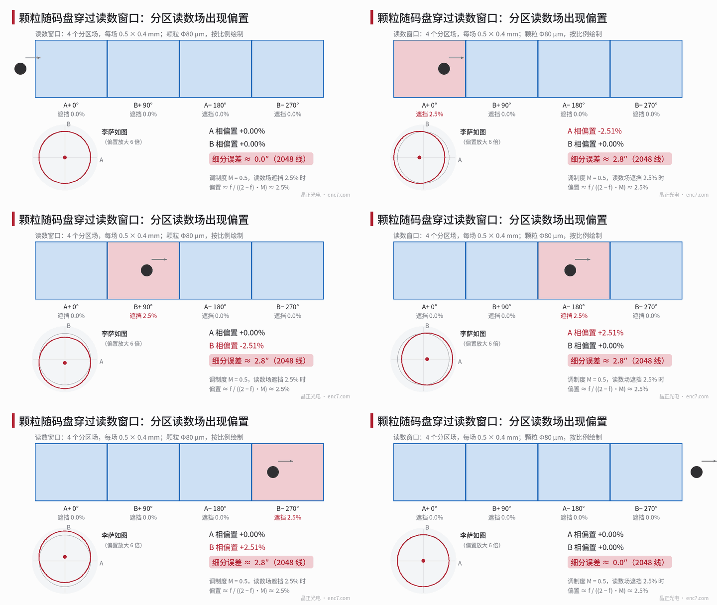
An 80 μm particle can add about 2.8″ of interpolation error on a 2048-line encoder—provided the readhead uses partitioned scanning fields. This article builds a signal model for occlusion and scattering, derives the relation offset ≈ f/(2M), and compares partitioned versus single-field scanning and particles versus oil-film stains with worked examples.
After assembly a particle of a few tens of micrometres, or a fingerprint, may land on the encoder disc. The same contamination leaves some encoders almost unaffected and produces in others a few arcseconds of error bump at a particular angle—or, in severe cases, lost counts. Where does the difference lie? To answer that, “dirty” must be turned into quantities that can be calculated: how much area is occluded, how much light is scattered, and how the readhead converts those changes into offset and amplitude error.
Signal model
Take four partitioned scanning fields that output photocurrents of phase 0°, 90°, 180° and 270°:
I_k = D·[1 + M·cos(φ − ψ_k)]
where D is the DC component, M the modulation depth, φ the electrical angle and ψ_k the phase of each field. After differencing
A = I_0° − I_180° = 2DM·cosφ, B = I_90° − I_270° = 2DM·sinφ
the DC component cancels completely. If a particle occludes a fraction f of the A+ field area and is much larger than the grating pitch, DC and AC of that field fall in the same proportion:
A = −f·D + (2 − f)·DM·cosφ
so channel A acquires a relative offset ε = f / ((2 − f)·M) ≈ f/(2M), while A and B amplitudes become unequal with a relative difference of about f/2. From the error laws of sine/cosine interpolation, offset produces a 1-per-period error of amplitude about ε rad; amplitude inequality produces a 2-per-period error of about f/4 rad. At 2048 lines, 1 rad of electrical angle is about 100.7″.
Two direct corollaries follow: error is proportional to 1/M, so lower modulation depth means more fear of dirt; and error comes from “phases being affected inconsistently”—if contamination treats all four phases alike, only amplitude falls and no offset appears.
Worked example: particles
Assume a single scanning field of 0.5 mm × 0.4 mm (0.2 mm²) and M = 0.5 (assumed):
| Particle diameter | Occlusion fraction f | Offset ε | Max. interpolation error (2048 lines) |
|---|---|---|---|
| 50 μm | 0.98% | about 1.0% | about 1.1″ |
| 80 μm | 2.5% | about 2.5% | about 2.8″ |
| 150 μm | 8.8% | about 9.2% | about 10″ |
The last column comes from a full atan2 calculation including both offset and amplitude inequality. When M falls to 0.3, the error from an 80 μm particle rises to about 4.4″ (Figure 2).
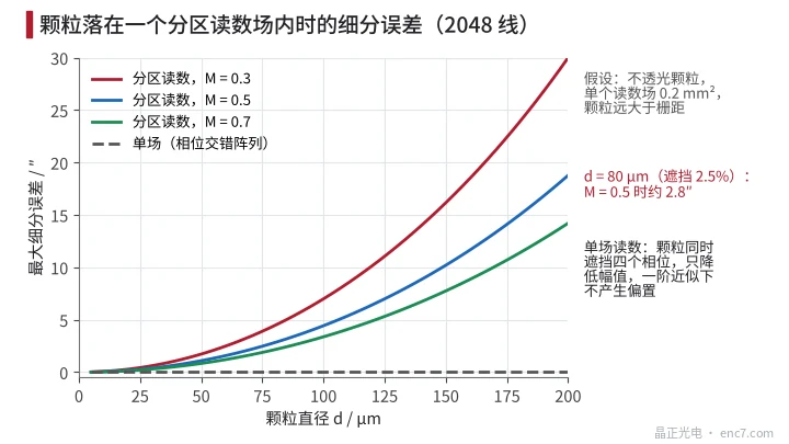
Compare single-field scanning: if the detector is a photodiode array with the four phases interleaved, the same area produces all four signals at once; a particle larger than the array period occludes all four phases in equal proportion and A, B only fall in amplitude together. The same 80 μm particle in a 0.8 mm² single-field window drops amplitude by only about 0.6%.
A few further details matter:
- Particle on the disc or on a stationary part: a particle on the disc passes once per revolution, so the error bump sits at a fixed angle for a very short time and a slow automatic offset correction cannot catch it; a particle on the index grating or window produces a constant offset that correction can absorb.
- Particle smaller than the pitch: the effect depends on where it lands. On a transmissive disc a small particle sitting on a chrome line barely blocks any extra light.
- Square-wave output: offset ε shifts the comparator trip point and the duty cycle departs by about arcsin(ε)/π; at ε = 2.5% that is about 0.8% of a period. Too large an amplitude drop also approaches the comparator hysteresis and can cause lost pulses.
Oil films and fingerprints: a scattering model
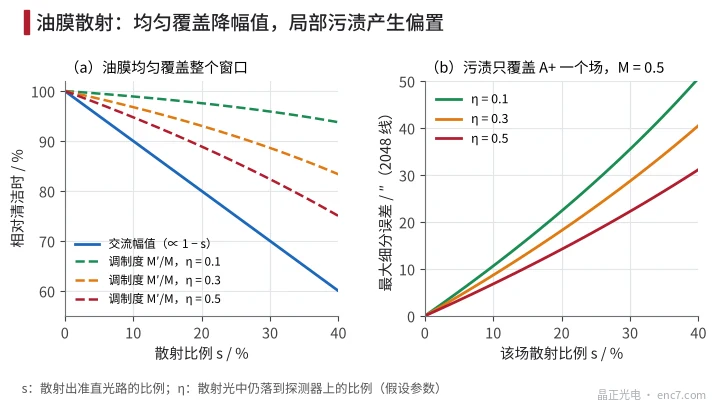
Oil films and fingerprint residue mainly scatter rather than block light. Suppose a fraction s of the collimated light through the contaminated zone is scattered out of the optical path, and a fraction η of that scattered light still reaches the detector as unmodulated background; then AC is proportional to (1 − s) and DC to (1 − s) + η·s, and the modulation depth becomes
M′ / M = (1 − s) / [(1 − s) + η·s]
Uniform coverage of the whole window: at s = 30%, η = 0.3, AC amplitude falls to 70% and modulation depth to 89% of the original, with no offset. If the encoder has automatic gain control, LED drive current must rise by about a factor of 1.4 to compensate—accelerating LED lumen depreciation.
Coverage of one partitioned field only: that field’s DC changes by −s·(1 − η)·D and the relative offset is s·(1 − η) / ((2 − s)·M). At s = 10%, η = 0.3, M = 0.5 the offset is about 7.4% and the fully computed maximum interpolation error about 8.7″ (Figure 3). A local stain is far more dangerous than a uniform oil film.
The same applies to reflective discs: an oil film changes reflectance and scattering, and condensate droplets scatter even more strongly. At 25 ℃ and 60% relative humidity the dew point of air is about 16.7 ℃; a disc surface colder than that will dew.
Engineering points
- When assessing contamination sensitivity, look first at readhead architecture: partitioned scanning fields are sensitive to local contamination; a single-field phase-interleaved array shows, for contamination larger than the array period, essentially only an amplitude drop.
- Offset is about f/(2M): raising modulation depth or enlarging a single scanning-field area both reduce the error from a given particle in proportion.
- Disc cleanliness should be back-calculated from scanning-field area: for a 0.2 mm² field, M = 0.5 and contamination error required below 1″, the disc should not carry opaque particles larger than about 45 μm.
- Fingerprints and local oil stains are more dangerous than a uniform film; bare-hand contact with the track zone is forbidden in assembly, and after cleaning check for streak residues left by wiping.
- Encoders with automatic gain should monitor LED drive current; a sustained rise can be a signal of contamination or lumen depreciation.
- In testing, simulate contamination with standard particles or local opaque masks, measure offset and interpolation error, and verify design margin.
Summary
Contamination effects can be quantified: particles change each phase’s DC and AC by the occlusion fraction f, oil films by the scattered fraction s. When phases are affected inconsistently, offset of about f/(2M) appears, and at 2048 lines a particle of a few tens of micrometres already maps to arcsecond-level error; when phases are affected alike, only amplitude falls. Scanning-field architecture, modulation depth and cleanliness control together set how much contamination an encoder can tolerate.
Translated from the ENC7 Chinese technical library (article 0197). Read the Chinese original. Need a disc built to your drawing? Request a quote or see our custom encoder discs.
© Langfang Jingzheng Optoelectronic Technology Co., Ltd. All rights reserved. This article was created with AI assistance.