Industry applications in depth
Radiotherapy accelerator gantry and collimator rotation: angle requirements at a 1 mm isocentre
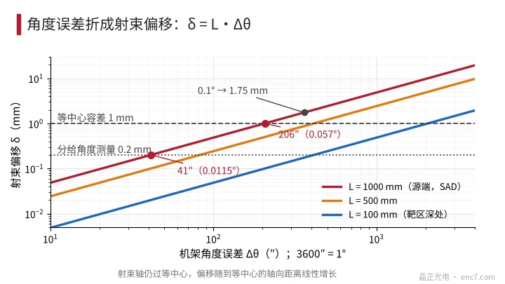
A gantry angle error Δθ rotates the beam about the isocentre, and the offset at a distance L along the axis is L·Δθ: at L = 1 m, 0.1° corresponds to 1.75 mm. This article converts a 1 mm budget into an angular specification, derives the upper and lower bounds of the dual-encoder difference alarm threshold, and discusses the effect of the radiation environment on the encoder disc and the readhead.
The gantry of a radiotherapy accelerator rotates about the isocentre, so that the beam converges on the target from every direction, while the collimator rotates about the beam axis to orient the field. The machine’s tolerance on the departure of the beam axis from the isocentre is usually of the order of 1 mm. Angle measurement is only one of the error sources, but it is the one on which the interlock depends most. This article first converts angular error into beam-position error, then works back to the resolution and accuracy of the encoder, and finally discusses how to set the dual-encoder difference alarm threshold and what problems the radiation environment can cause. All figures are examples.
How angular error becomes a beam offset
Any angular error Δθ about the axis produces, at a point a distance L from the axis of rotation, a displacement
δ = L·Δθ (Δθ in radians, small angles)
The gantry axis passes through the isocentre. If the gantry angle is in error by Δθ, the entire beam rotates by Δθ about the isocentre. The beam axis still passes through the isocentre, but the transverse offset at a distance z from the isocentre along the axis is z·Δθ: at the source, z = SAD ≈ 1 m; deep in the target, z is only some tens to a little over a hundred millimetres. The collimator’s axis of rotation is the beam axis, and the lever arm is the distance ρ of the field edge from the axis, ρ = 100–200 mm.
| Angular error | Source end L = 1000 mm | L = 500 mm | L = 100 mm (deep in the target, field edge) |
|---|---|---|---|
| 0.01° (36″) | 0.17 mm | 0.09 mm | 0.017 mm |
| 0.05° (180″) | 0.87 mm | 0.44 mm | 0.087 mm |
| 0.1° (360″) | 1.75 mm | 0.87 mm | 0.17 mm |
| 0.5° | 8.7 mm | 4.4 mm | 0.87 mm |
Taking the longest lever arm L = SAD as a conservative estimate, 0.1° is already about 1.7 mm. The offset actually experienced in the target is much smaller, but the field-defining components are near the source, and the interlock is also set at this order of magnitude, see Figure 2.
Budget allocation and encoder specifications
Assume the machine allows the beam axis to depart from the isocentre by 1 mm, of which mechanical items such as gantry sag and bearing runout take the larger share, and 0.2 mm is allocated to angle measurement (an assumption). Converted at L = 1 m:
δθ ≤ 0.2 mm / 1000 mm = 200 μrad ≈ 41″ (0.0115°)
For the collimator, converted at ρ = 200 mm, the same 0.2 mm corresponds to 206″ (0.057°), so the specification can be relaxed by a factor of five. The resolution should be about one order of magnitude finer than the budget, around 4″: 18 bits give 4.94″ per count, which is slightly coarse, and 19 bits give 2.47″, so 19 bits or more on the gantry axis is the more robust choice. The accuracy (including eccentricity, joints and the transmission) must fall within 41″; the accuracy of the encoder itself can take only about half of that, for example ±20″.
There are two ways to measure: a large-bore encoder mounted directly on the gantry axis, or measurement through a take-off gear. In the latter case the encoder’s own error is reduced by the gear ratio i, but backlash and transmission error of the gear are also referred to the gantry, so if the gantry axis can be measured directly, it should be.
Dual-encoder redundancy and the alarm threshold
Channel A is used for control and an independent channel B for monitoring; the difference is D = θ_A − θ_B. When each channel has a random error σ, the noise of the difference is σ_d = √2·σ; for σ = 20″, σ_d = 28″.
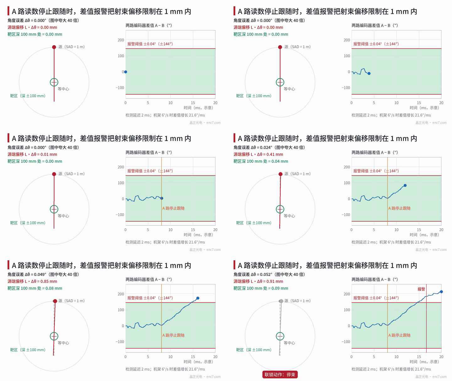
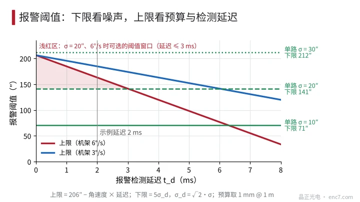
The worst fault is that channel A stops following while the gantry continues to move. Assume a maximum gantry speed of 6°/s (1 r/min, an assumption); the difference then grows at 21.6″/ms. Before the alarm there is still a detection delay t_d (the sum of the sampling period, debounce and interlock response), during which the difference continues to grow. The alarm threshold θ_th must satisfy both:
θ_th ≥ 5σ_d (lower bound, to avoid false alarms; a factor of 5 is an example choice)
θ_th + ω_g·t_d ≤ θ_bud (upper bound; θ_bud is 1 mm at 1 m, that is 206″)
For σ = 20″ and t_d = 2 ms the lower bound is 141″ and the upper bound is 206 − 43 = 163″; 0.04° (144″) is chosen. At the alarm the difference is about 187″ (0.052°), corresponding to a source-end offset of 0.91 mm, still within 1 mm (Figure 1). The window is narrow: if σ increases to 30″, the lower bound rises to 212″, which is above the upper bound, and there is no solution; if the delay increases to 3 ms or more, the window for σ = 20″ also disappears, see Figure 3. This shows that encoder accuracy and detection delay must be designed together; the threshold alone is not enough.
The independence of the two channels is equally important: they must not share the supply, the readhead, the cable or the processing circuitry. Two channels that work on different principles are better at avoiding common-cause failures, and the difference must not be computed by one channel’s own circuitry.
The radiation environment
The treatment head of the accelerator produces high-energy photons, and at higher beam energies photoneutrons are also generated in the target and the shielding. The encoder, near the gantry axis, sees leakage and scattered radiation, far less than the primary beam, but the accumulated dose is not zero. Possible effects include:
- the transmittance of a glass encoder disc falls and the glass browns as colour centres increase; radiation-hard grades exist and must be verified against the dose;
- the dark current of the photodiode increases and the output of the light source decays, so the amplitude falls slowly;
- single-event upsets in memory and FPGAs can occasionally corrupt the absolute position or the configuration;
- adhesives and plastics age and become brittle.
The actual dose depends on the machine type and the mounting position; it should be measured or supplied by the machine builder. This article does not give figures. Relevant safety standards (for example IEC 60601-2-1) have further requirements on interlocks and indication; the original text of the standard governs.
Engineering points
- First convert the machine budget into an angle: 1 mm at 1 m is 206″, and the 0.2 mm allocated to angle measurement is 41″.
- Take the resolution at about 1/10 of the budget, and use 19 bits or more for the gantry-axis encoder; the collimator, converted at ρ = 200 mm, can be relaxed.
- Take the threshold between 5σ_d and θ_bud − ω_g·t_d; if the window is too narrow, change to a more accurate encoder or shorten the detection delay.
- Debounce by alarming only after several consecutive samples exceed the limit, but the debounce time must be included in t_d.
- Supply and process the two encoder channels independently, preferably on different principles; if the gantry axis can be measured directly, do not take off through a gear.
- Monitor the trend of the A²+B² amplitude; a slow decay caused by radiation can then give a warning before the counts go wrong.
In brief
Angular error is converted into a beam offset by δ = L·Δθ. Conservatively taking L = SAD, 0.1° corresponds to about 1.75 mm. Folding the 1 mm budget into an angular specification of about 41″ requires a resolution of 19 bits or more and an accuracy of the order of ±20″. The dual-encoder alarm threshold is squeezed between a noise lower bound and a budget upper bound; the window varies with detection delay and encoder accuracy. The effects of radiation on glass, photoelectric devices and memory must be assessed together with the choice of encoder.
Translated from the ENC7 Chinese technical library (article 0773). Read the Chinese original. Need a disc built to your drawing? Request a quote or see our custom encoder discs.
© Langfang Jingzheng Optoelectronic Technology Co., Ltd. All rights reserved. This article was created with AI assistance.