Industry applications in depth
SCARA first axis: how many microns at the tip per 1 arcsecond
Tip error on a SCARA is the combination of the two joint-angle errors after each has been amplified by its moment arm. This article derives σ_p = √(r²σ1² + L2²σ2²), splits ±10 μm between the two axes (3.6″ and 8.3″), refers the budget to the motor-side encoder at a reduction ratio of 80, and estimates a signal frequency of 205 kHz in a 60° reciprocation.
The end-effector repeatability specification of a SCARA is a length, for example ±10 μm, whereas the encoder specification is an angle. Only a moment arm stands between the two: when the distance from the first axis to the tip is 400 mm, 1″ is 400 mm × 4.848×10⁻⁶ = 1.94 μm. Starting from this conversion, this article allocates the tip specification to the two joints and then refers it back to the motor-side encoder, to see how fine and how accurate that encoder must be.
From angle to the tip: the Jacobian and the two-axis combination
The tip position is p = L1·(cosθ1, sinθ1) + L2·(cos(θ1+θ2), sin(θ1+θ2)), where L1 and L2 are the two arm lengths and θ1 and θ2 are the two joint angles. Partial derivatives with respect to the two joint angles give:
- ∂p/∂θ1: magnitude r (the distance from axis 1 to the tip), direction perpendicular to the line joining them;
- ∂p/∂θ2: magnitude L2, direction perpendicular to the second arm.
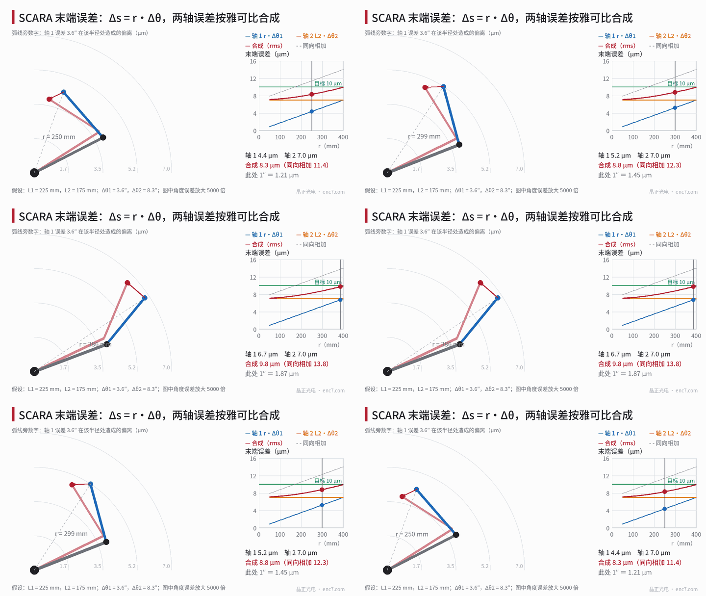
So the tip error Δp = J·Δθ has only a tangential component, not a radial one. When the two axis errors are independent, the RMS of the tip error vector is
σ_p = √(r²σ1² + L2²σ2²)
σ1 and σ2 are the standard deviations of the two joint-angle errors. The upper bound of same-sense addition of the two columns is r·σ1 + L2·σ2, which occurs when the arm is fully extended. σ_p depends only on r, so the error contours are concentric circles about the first axis (Figure 1).
Error budget: splitting ±10 μm between the two axes
The worked example takes L1 = 225 mm, L2 = 175 mm, and a maximum r = 400 mm. Treating ±10 μm as the combined upper bound and giving each axis 7 μm, the root-sum-square is 9.9 μm:
- Axis 1: 7 μm ÷ 400 mm → 1.75×10⁻⁵ rad = 3.6″;
- Axis 2: 7 μm ÷ 175 mm → 4.0×10⁻⁵ rad = 8.3″.
The angular budget is inversely proportional to the moment arm; the second arm is shorter, so a larger angular error is allowed. The contributions at each r are as follows:
| r | Axis 1 (3.6″) | Axis 2 (8.3″) | Combined | Same-sense sum |
|---|---|---|---|---|
| 100 mm | 1.75 μm | 7.0 μm | 7.3 μm | 8.8 μm |
| 200 mm | 3.49 μm | 7.0 μm | 7.9 μm | 10.5 μm |
| 300 mm | 5.24 μm | 7.0 μm | 8.8 μm | 12.3 μm |
| 400 mm | 6.98 μm | 7.0 μm | 9.9 μm | 14.0 μm |
Near in, axis 2 dominates; at full extension the two axes are comparable. It should be noted that repeatability concerns the scatter after each arrival at position; a static error of the encoder that is stable at the same position does not enter repeatability, but it does enter absolute accuracy; noise, backlash and thermal drift are the sources of repeatability.
Referred to the motor side: the reduction ratio relaxes the encoder by a factor of 80
Assume a reduction ratio N = 80 on axis 1. In the example the reducer’s repeatable error is taken as 2.5″ and structural plus thermal drift as 2.0″, so the budget left on axis 1 for encoder-related terms is
√(3.6² − 2.5² − 2.0²) = 1.65″
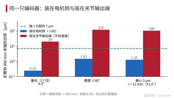
Referred to the motor side this is 1.65″ × 80 = 132″. Taking as an example a 17-bit unit (9.9″ per count), 2048 lines, accuracy ±60″, and a Ø30 mm encoder disc at r = 12 mm with 3 μm of eccentricity (first-order error 51.6″), the figures referred to the joint are:
| Item | Motor side | Referred to the joint | Referred to the tip at 400 mm |
|---|---|---|---|
| Quantization | 9.9″ | 0.12″ | 0.24 μm |
| Accuracy | ±60″ | 0.75″ | 1.45 μm |
| Eccentricity | 51.6″ | 0.64″ | 1.25 μm |
The root-sum-square of the three amplitudes is about 0.99″, which is less than 1.65″. A resolution criterion may be taken as q/N ≤ 1/5 of the encoder budget, i.e. q ≤ 26″, which a 16-bit unit (19.8″) already satisfies. If the same encoder is mounted at the joint output (Figure 2), the three terms are 19, 116 and 100 μm, all exceeding 7 μm; if axis 1 is changed to direct measurement at the output, a Ø100 mm encoder disc (r = 45 mm) has to hold eccentricity alone within 0.36 μm just to fill the 1.65″ budget, otherwise diametrically opposite dual readheads are needed.
Reciprocating motion: signal frequency and acceleration
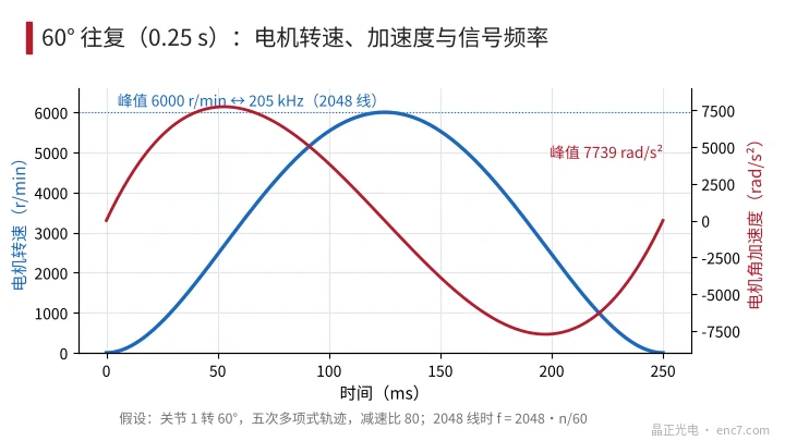
Assume joint 1 turns through 60° in 0.25 s, on a fifth-order polynomial trajectory. The peak joint angular velocity is 1.875·Δ/T = 7.85 rad/s (75 r/min), and the peak angular acceleration is 5.77·Δ/T² = 96.7 rad/s². Multiplied by the reduction ratio of 80, the motor peak speed is 6000 r/min and the peak angular acceleration is 7739 rad/s².
At 2048 lines the peak signal frequency is 205 kHz (f = N·n/60); as speed rises and falls the frequency changes at a rate of about 2.5 kHz/ms. The unlock condition of a tracking-loop interpolator is f_n ≥ √(N·α)/2π, which is about 634 Hz here, so a loop bandwidth of a few times that value is sufficient.
Path accuracy during the motion is also affected by sampling delay: at the peak of 7.85 rad/s, a delay of 62.5 μs corresponds to 101″, about 196 μm, and has to be handled by compensation; this is a different matter from repeatability after arrival at position.
Engineering takeaways
- First convert with Δs = L·Δθ: at 400 mm, 1″ ≈ 1.94 μm; at 175 mm, 1″ ≈ 0.85 μm; the angular budget is inversely proportional to the moment arm.
- When the two joint errors are independent, combine them as √(r²σ1² + L2²σ2²); with the arm fully extended, r is largest and the two columns add in the same sense, which is the most unfavourable pose.
- At a reduction ratio of 80, a 17-bit motor-side encoder of accuracy ±60″ refers to only about 1 μm at the tip, far smaller than the reducer and structural terms, so a higher resolution is not needed.
- Distinguish repeatability from absolute accuracy: repeatability is about noise, backlash and thermal drift; absolute accuracy is about eccentricity and graduation error.
- If reduction is omitted on axis 1 and the angle is measured directly at the output, both disc eccentricity and accuracy requirements tighten by a factor of about 80, so a large-diameter encoder disc and diametrically opposite dual readheads should be used.
- Under high-acceleration reciprocation, size the front-end bandwidth from f = N·n/60, and size the tracking-loop bandwidth from √(N·α)/2π.
Closing
A SCARA converts a micrometre specification at the tip into an arcsecond specification at the joints, and the conversion factor is the moment arm: at 400 mm, 1″ is about 1.94 μm. The two-axis combination is the root-sum-square of the contributions through each moment arm; in the example, ±10 μm at the tip corresponds to 3.6″ on axis 1 and 8.3″ on axis 2. With a reduction ratio, the resolution and accuracy required of the motor-side encoder are relaxed by two orders of magnitude, and the difficulty shifts to reducer repeatability, thermal drift and delay compensation.
Translated from the ENC7 Chinese technical library (article 0763). Read the Chinese original. Need a disc built to your drawing? Request a quote or see our custom encoder discs.
© Langfang Jingzheng Optoelectronic Technology Co., Ltd. All rights reserved. This article was created with AI assistance.