Encoder-disc terminology
Spatial Frequency and MTF: Why Smaller Pitch Weakens the Signal

The spatial frequency of an encoder-disc grating is ν = 1/p; the MTF of the reading optics at ν sets the upper bound on signal modulation. This article derives diffraction-limited, defocus and gap-blur MTF: at NA 0.1 a 20 μm pitch gives about 0.72 and 8 μm about 0.34, and explains the factor-of-two error from mixing “lines/mm” with “line pairs/mm”.
Move the same reading optics from a 20 μm-pitch disc to an 8 μm-pitch disc and the signal amplitude often does not fall a little—it falls by more than half, and a slight further misfocus nearly kills it. Intuitively “finer lines, optics cannot resolve them”; quantitatively the reading optics are a spatial low-pass filter, and the smaller the pitch the higher the spatial frequency that carries the signal and the more it is attenuated. The tool that describes this is the modulation transfer function (MTF).
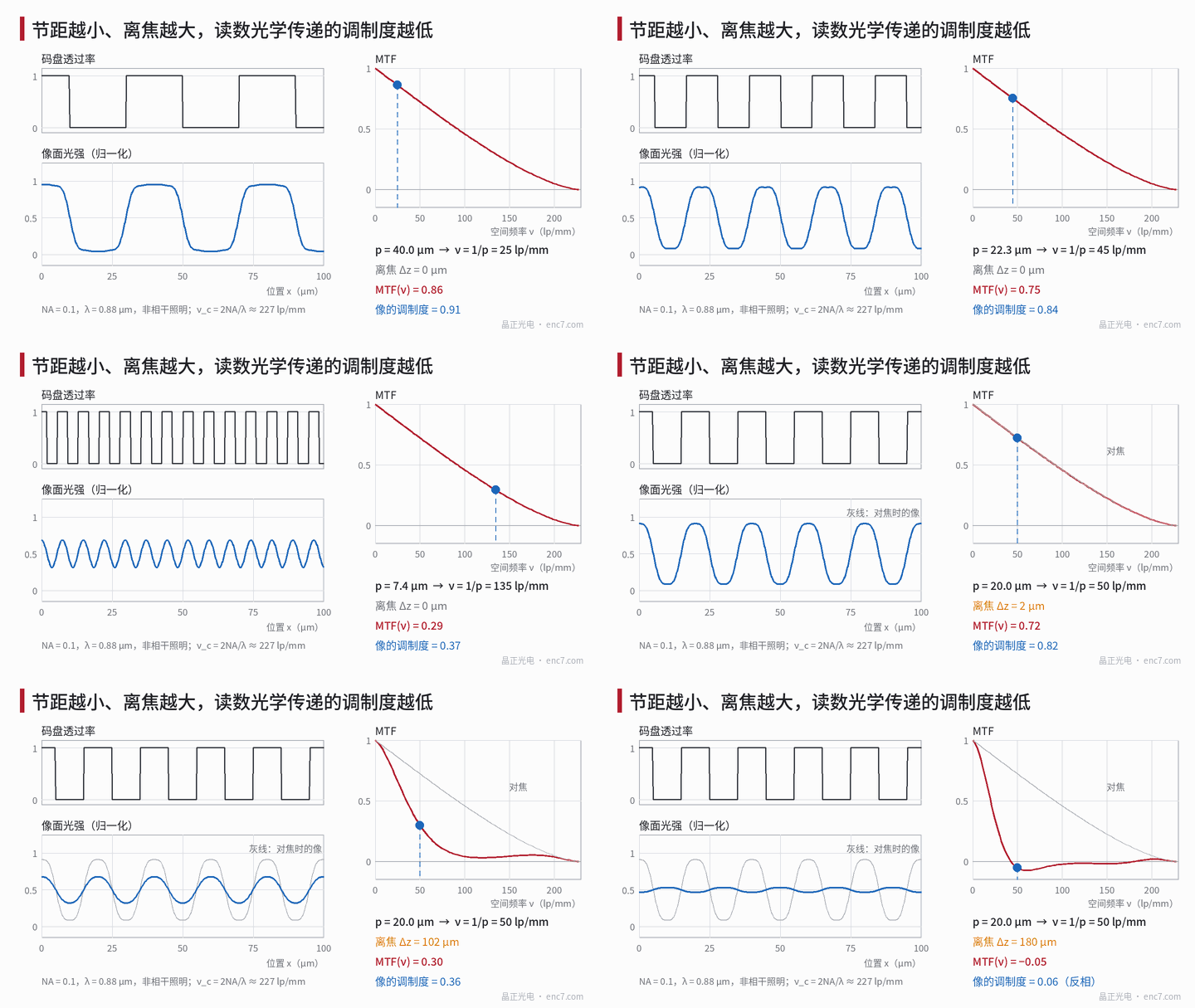
Spatial frequency: ν = 1/p, and two kinds of “line”
The spatial frequency of an encoder-disc grating is
ν = 1/p
in line pairs per millimetre (lp/mm) or cycles per millimetre. A 20 μm pitch is 50 lp/mm, 8 μm is 125 lp/mm, 4 μm is 250 lp/mm. On a radial disc ν = N/(2πr) varies with radius—slightly higher at the inner edge of a track, slightly lower at the outer.
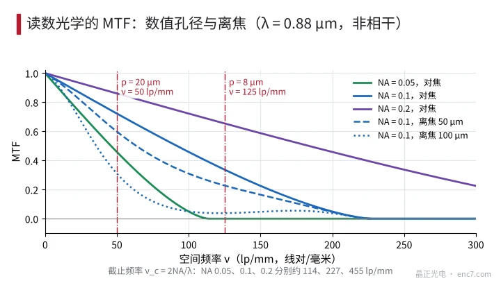
In the encoder industry a “line” is one period, so “lines/mm” and “line pairs/mm” have the same numerical value; in optics and camera practice a “line” often counts one dark and one bright line each as a line, so “100 lines/mm” is only 50 lp/mm. Mixing the two is a factor-of-2 error. At NA = 0.1, MTF(50 lp/mm) = 0.72 and MTF(100 lp/mm) = 0.46; MTF(125 lp/mm) = 0.34, and 250 lp/mm already exceeds the cutoff. Reading the frequency wrong by a factor of two can make a feasible design look unfeasible, or the reverse. “Resolve 10 μm” must also clarify whether that is line width or pitch.
The modulation chain: MTF only at the fundamental
Incoherent imaging is linear in intensity: a sinusoidal object component at spatial frequency ν reaches the image with amplitude multiplied by MTF(ν). Disc transmittance is a square wave and expands into a fundamental plus 3rd, 5th… harmonics; an encoder uses only the fundamental, so
M_signal ≈ M_object,fund × MTF_optics(1/p) × MTF_defocus(1/p) × MTF_det(1/p)
where a 50% duty-cycle, full-contrast square wave has fundamental modulation 4/π ≈ 1.27; MTF_det is the contribution of the detector-element aperture, sinc(w/p) for element width w, about 0.64 when w = p/2. Using the square-wave image contrast (Imax − Imin)/(Imax + Imin) in place of MTF is a common error—that is the contrast transfer function (CTF) and overestimates at mid and low frequencies.
Harmonics are attenuated more—free filtering: at NA = 0.1 and 20 μm pitch the ratio of 3rd harmonic to fundamental in the image falls from the square-wave 1/3 to about 10.4%; at 8 μm pitch the 3rd harmonic (375 lp/mm) exceeds cutoff and the image is nearly pure sinusoid.
Diffraction-limited MTF
For a circular pupil, incoherent illumination and no aberration:
MTF(ν) = (2/π)·[arccos(x) − x·√(1 − x²)], x = ν/ν_c, ν_c = 2NA/λ
where NA is the object-side numerical aperture and λ the wavelength. At λ = 0.88 μm:
| NA | Cutoff ν_c | 20 μm (50 lp/mm) | 8 μm (125 lp/mm) |
|---|---|---|---|
| 0.05 | 114 lp/mm | 0.46 | 0 |
| 0.1 | 227 lp/mm | 0.72 | 0.34 |
| 0.2 | 455 lp/mm | 0.86 | 0.65 |
MTF = 0.5 corresponds to x ≈ 0.404, so one needs NA ≥ λ/(0.808·p) ≈ 1.09/p (p in μm): 0.054 for 20 μm, 0.136 for 8 μm, 0.27 for 4 μm. Halve the pitch and double the NA (see Figure 2).
Defocus and gap blur
Defocus in imaging readout. Object-side defocus Δz produces wave aberration W20 = Δz·NA²/(2λ) at the pupil edge. Numerical pupil autocorrelation at NA = 0.1: for 20 μm pitch MTF falls to 80% of the in-focus value at about 55 μm defocus and crosses zero at about 160 μm; for 8 μm pitch about 40 μm and 115 μm. At NA = 0.2 the in-focus MTF is higher, but the 80% depth of focus shrinks to about 24 μm at 20 μm pitch and only about 12 μm at 8 μm (see Figure 3 right). The geometric blur-circle approximation 2J1(πbν)/(πbν) (b = 2NA·Δz) is badly wrong when W20 is less than about one wavelength: at NA = 0.1, 50 μm defocus and 8 μm pitch the geometric estimate gives about 0 while wave optics gives 0.23.
After MTF crosses zero it is negative—image contrast reverses—so simultaneous polarity flip of A and B is equivalent to a half-period position shift; focusing by “maximum amplitude” can stop on a side lobe with small amplitude and reversed phase.
Gap blur in imaging (shadow) readout. Without an imaging lens, residual divergence of the collimated light smears the shadow. For a square emitter of width s and collimator focal length f the full divergence angle is Δθ ≈ s/f, and the blur width at gap g is g·Δθ:
MTF_gap = sinc(g·Δθ/p)
Assuming s = 0.2 mm and f = 5 mm (Δθ = 0.04 rad): at g = 0.1 mm, 20 μm pitch gives 0.94 and 8 μm gives 0.64; at g = 0.2 mm the values are 0.76 and 0—the latter blur width equals exactly one pitch (see Figure 3 left). This factor must still be multiplied by the near-field diffraction factor; see the Talbot-effect article in this library.
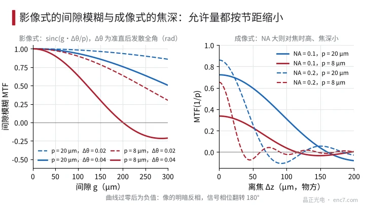
Gap blur depends only on the ratio of blur width to pitch, so allowed gap scales with pitch—at 8 μm about two-fifths of that at 20 μm; imaging defocus, while wave aberration is less than one wavelength, is also constrained by λ/NA², and at NA = 0.1 the depth of focus at 8 μm pitch is about seven-tenths of that at 20 μm. Both tolerances shrink with pitch.
Measurement: how to measure the MTF of reading optics
- Multi-pitch test piece: several pitches at the same read radius (e.g. 40, 20, 10, 8 μm); read the image fundamental amplitude and divide by the object fundamental. Prefer computing the object fundamental from a high-magnification microscope duty-cycle measurement rather than using 4/π directly.
- Knife-edge method: photograph a straight chrome edge, form the edge-spread function, differentiate to the line-spread function, then Fourier-transform for a continuous MTF curve (same idea as ISO 12233).
- Through-focus scan: step the gap or focal plane, record the MTF(1/p) curve, and locate the main peak and its tolerance.
Watch: detector-array sampling adds pixel MTF and aliasing; collimated LED illumination is partially coherent, so intensity imaging is not strictly linear and the incoherent MTF is only an approximation. Coherent illumination has cutoff NA/λ—half the incoherent value—while the fundamental in the passband is almost unattenuated.
Engineering points
- Unify drawings and optical specifications on lp/mm (cycles/mm); convert pitch to ν = 1/p; do not write ambiguous “lines/mm”.
- At λ = 0.88 μm, diffraction-limited MTF ≥ 0.5 needs NA ≥ 1.09/p (p in μm); halve the pitch and double the NA.
- Judge the signal by MTF(1/p) at the fundamental, not by square-wave contrast; low MTF at higher harmonics is free harmonic filtering.
- Raising NA improves in-focus MTF but shrinks depth of focus roughly as 1/NA²—trade against installation gap tolerance.
- Allowed gap for imaging readout scales as p/Δθ; at fine pitch either shrink the emitter and lengthen the collimator, or reduce the gap.
- Focus by scanning from the large-defocus side to find the main peak; avoid stopping on a reversed-contrast side lobe.
Summary
As pitch shrinks, the spatial frequency ν = 1/p that carries the signal rises and the MTF of the reading optics falls with it: at NA = 0.1 a 20 μm pitch gives about 0.72 and 8 μm only 0.34. Gap blur makes allowed gap proportional to pitch; defocus shrinks depth of focus with both pitch and NA. Convert pitch to lp/mm and multiply the fundamental MTFs stage by stage, and the upper bound on signal modulation can be estimated at the design stage.
Translated from the ENC7 Chinese technical library (article 0263). Read the Chinese original. Need a disc built to your drawing? Request a quote or see our custom encoder discs.
© Langfang Jingzheng Optoelectronic Technology Co., Ltd. All rights reserved. This article was created with AI assistance.