Introduction to encoder principles
The Z Index Pulse: A Landmark Once per Revolution
Channels A and B produce several thousand identical pulses each revolution; they can be counted as “how far”, but they cannot say “where”. Channel Z produces only one pulse per revolution and is the landmark on the disc. This article covers the structure of the index track, the width and gating of the Z pulse, the homing sequence, and other uses of Z.
An incremental encoder has a built-in shortcoming: after a power loss it does not know where it has stopped. Channels A and B produce several thousand pulses each revolution, all alike, so the controller can only count “how far it has gone”, not say “where it is now”.
That is why machine tools, placement machines and similar equipment often have to “home” after power-up. Homing relies on a third signal: channel Z, also called the index pulse, the reference pulse or the index mark.
The index track: only one window in the whole revolution
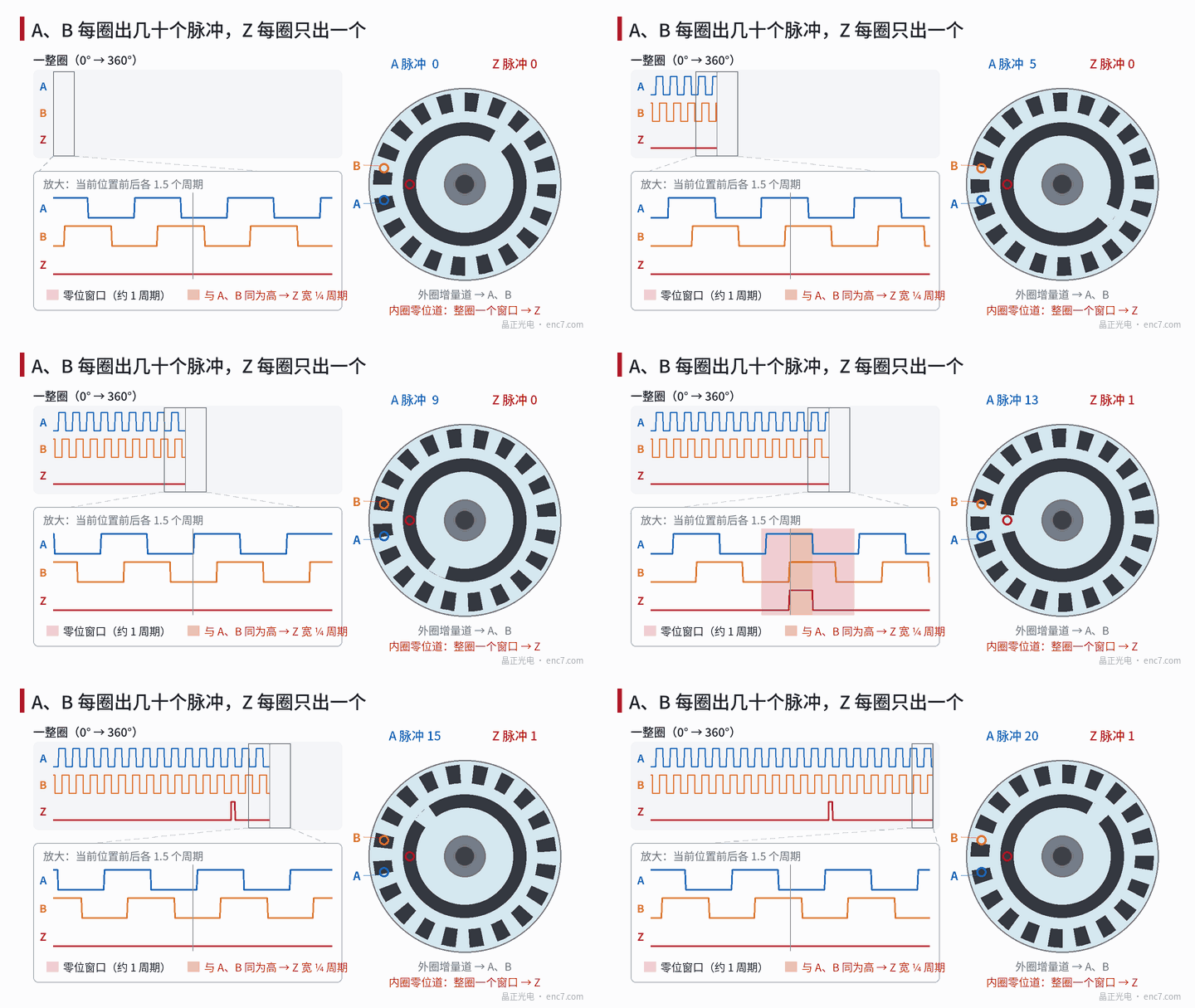
On an incremental disc, besides a ring of equally spaced incremental lines, there is usually a separate index track. Unlike the incremental track, the index track is opaque almost all the way around and opens only one transmitting window at one position (it can also be made as a single line). The readhead has a Z channel at the corresponding place; once per revolution the window passes and Z produces one pulse; see Figure 1.
On a disc made by photolithography, the index window and the incremental lines are formed on the same photomask, in the same exposure, so their relative position is fixed. That matters: in which cycle of the A and B waveforms Z appears, and in which segment of that cycle, is decided by the disc pattern and will not drift in use.
How wide is the Z pulse
The signal taken directly from the index window is generally about one signal cycle wide (it depends on the window design), and its edges are not as steep as those of A and B. Inside the encoder it is often “gated” with A and B: Z is output only when the index signal, A and B are all high at once. The Z thus obtained is only ¼ cycle wide and coincides with one of the four states of A and B.
Why so narrow? Because the controller often counts with fourfold decoding, so one cycle is 4 counts. If Z were 1 cycle wide it would span 4 counts and it would be ambiguous which of them is the zero; with Z ¼ cycle wide it coincides with only 1 count, and the zero is definite.
Product documentation often states the Z width as 90° or 360° of electrical angle, and which state it is aligned to also varies; selection and wiring follow the documentation.
Homing: a switch finds the turn, Z fixes the point
Z appears once every revolution, so Z alone cannot tell which turn it is. Homing therefore usually has several steps; see Figure 2:
- The shaft moves at high speed, looking for the origin switch (also called a deceleration stop);
- After hitting the switch it slows down;
- It continues at low speed, waiting for a Z pulse;
- The first Z after the switch arrives, the shaft stops and the count is cleared; this is the origin.
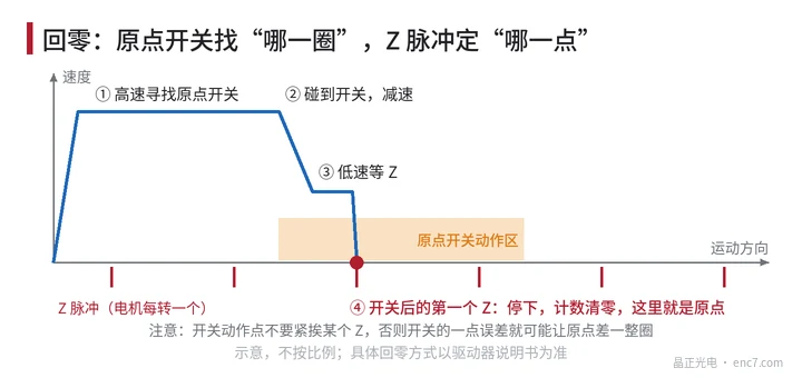
The switch finds “which turn”; Z fixes “which point”. The actuation point of a mechanical switch has some scatter, whereas the position of Z is decided by the disc pattern and repeats much more closely.
A worked example: on a 2500-line encoder one cycle is 360° ÷ 2500 = 0.144°, and the gated Z is ¼ cycle wide, that is 0.036°. If it drives a leadscrew with a 10 mm lead, one cycle corresponds to 4 μm and the Z width to 1 μm.
One point to watch: the switch actuation point should not sit close to a particular Z. Otherwise a little scatter in the switch may stop on this Z one time and on the next Z the next time, and the origin will be out by a whole revolution — 10 mm on the leadscrew.
Z can also be used to check for lost counts
Z appears once per revolution, so the count between two Z pulses should be exactly the line count × 4. For 2500 lines that is 10 000 counts. If a particular revolution comes out as 9998 or 10 003, the signal was disturbed or counts were lost, and the controller can raise an alarm.
In brief
Channel Z is a once-per-revolution pulse produced by a window on the index track of the disc, often gated to ¼ cycle wide so that it lines up with one definite count. In homing, an origin switch first finds which turn, and Z then fixes the exact point. The index window and the incremental lines are formed in the same photolithography step; that is the basis on which Z can serve as a “landmark”.
Translated from the ENC7 Chinese technical library (article 0004). Read the Chinese original. Need a disc built to your drawing? Request a quote or see our custom encoder discs.
© Langfang Jingzheng Optoelectronic Technology Co., Ltd. All rights reserved. This article was created with AI assistance.