Encoder-disc terminology
Thermal Drift Coefficients: Zero, Scale and Amplitude Coefficients
Temperature specifications often mix zero drift (″/K), scale drift (ppm/K) and the amplitude temperature coefficient (%/K). This article explains their origins and magnitudes, derives a least-squares separation of the zero and scale terms from the error difference at two temperatures, and notes that the zero term depends on the origin while a full revolution has no scale term.
One specification writes “temperature coefficient 0.1″/K”, another “thermal drift 3 ppm/K”, and a third “signal temperature drift −0.4%/K”. The three numbers have different units and are not the same quantity: the first is a rigid shift of the reading, the second is an error that grows in proportion to travel, and the third is a change in signal amplitude that does not itself alter the position reading. Only when they are separated can one tell where temperature is consuming accuracy, and who should compensate for it.
Definitions of the three coefficients
Let the error at position x (linear, mm) or θ (rotary, °) and temperature T be e(x, T). After a temperature change ΔT:
e(x, T + ΔT) − e(x, T) ≈ (Z + S·(x − x0))·ΔT + remaining terms
- Zero drift Z: the part of the difference that does not depend on position, in μm/K or ″/K. The reading shifts as a whole, equivalent to a movement of the reference point.
- Scale drift S: the part of the difference that is proportional to x − x0, in ppm/K (μm/m/K). The error grows linearly with distance from the origin.
- Amplitude temperature coefficient K_A: the relative rate of change of signal amplitude, in %/K. It does not appear in the equation above; it affects the signal-to-noise ratio, interpolation error and alarm margin.
- Remaining terms: nonlinear thermal deformation such as bending, changes in the harmonics of a rotary error, and measurement repeatability.
x0 is the origin. From the equation, a shift of the origin by Δx changes Z by S·Δx, so zero drift must be reported together with the origin (reference mark or fixed point).
Origins and magnitudes
Zero drift: thermal deformation of the bracket. The readhead bracket has a thermal-expansion path of length L in the measuring direction. If the difference in expansion coefficients of the two materials is Δα, the readhead moves tangentially by Δα·L·ΔT and the reading of a rotary encoder changes by Δα·L·ΔT/r. Example: L = 10 mm, an aluminium bracket on a stainless-steel seat (Δα about 7 ppm/K), r = 20 mm, giving about 0.72″/K. On a linear scale the fixed point itself also moves as the machine bed expands. Axial expansion under oblique illumination can likewise couple into zero drift (see the article on temperature effects in this library).
Scale drift: expansion mismatch, and it must be clear relative to what. For a linear scale fixed at one end and free to expand elsewhere, the reading ≈ X·(1 − α_s·ΔT), where X is the physical position and α_s the expansion coefficient of the scale. If the reference is a laser interferometer corrected to physical length, S = −α_s; if what matters is workpiece size at 20 ℃ and the workpiece and machine have expansion coefficient α_m, then S = α_m − α_s. A glass scale (about 8–9 ppm/K) on a steel machine (about 11–12 ppm/K) gives about −9 ppm/K on the first basis and about +3 ppm/K on the second — different in both sign and magnitude. Rigid bonding of the scale to the base is yet another case (for the difference between floating and bonded mounting, see the article on linear scales in this library).
A rotary encoder has no scale term over a full revolution. Uniform expansion does not change the angular position of radial graduation lines, and the pitch at a fixed read radius is also unchanged; moreover a full-revolution error must close, e(0°) = e(360°), so a term that grows linearly with angle cannot exist. Expansion mismatch between the encoder disc and the hub appears as a change in eccentricity (first harmonic); uneven loading of the hub appears as a second harmonic. A scale term that grows with angle and jumps back at the joint appears only when a length of code strip is wrapped into a circle, fixed at one end, and the strip and the drum have different expansion coefficients.
Amplitude temperature coefficient: dominated by the light source. The optical-power temperature coefficient of a near-infrared LED is commonly −0.3 %/K to −0.6 %/K in device data. At −0.4 %/K, after a 60 K rise the amplitude falls to about 79%. The responsivity temperature coefficient of a silicon detector in the near infrared is positive but smaller, and the LED wavelength shift with temperature (about 0.2–0.3 nm/K) has little effect on the gap window of imaging-type scanning. What really affects accuracy is the difference between the amplitude temperature coefficients of channels A and B: a difference of 0.01 %/K produces an amplitude mismatch of 0.8% after 80 K, and about 0.4″ of second-harmonic interpolation error at 2048 lines.
Separating the zero and scale terms at two temperatures
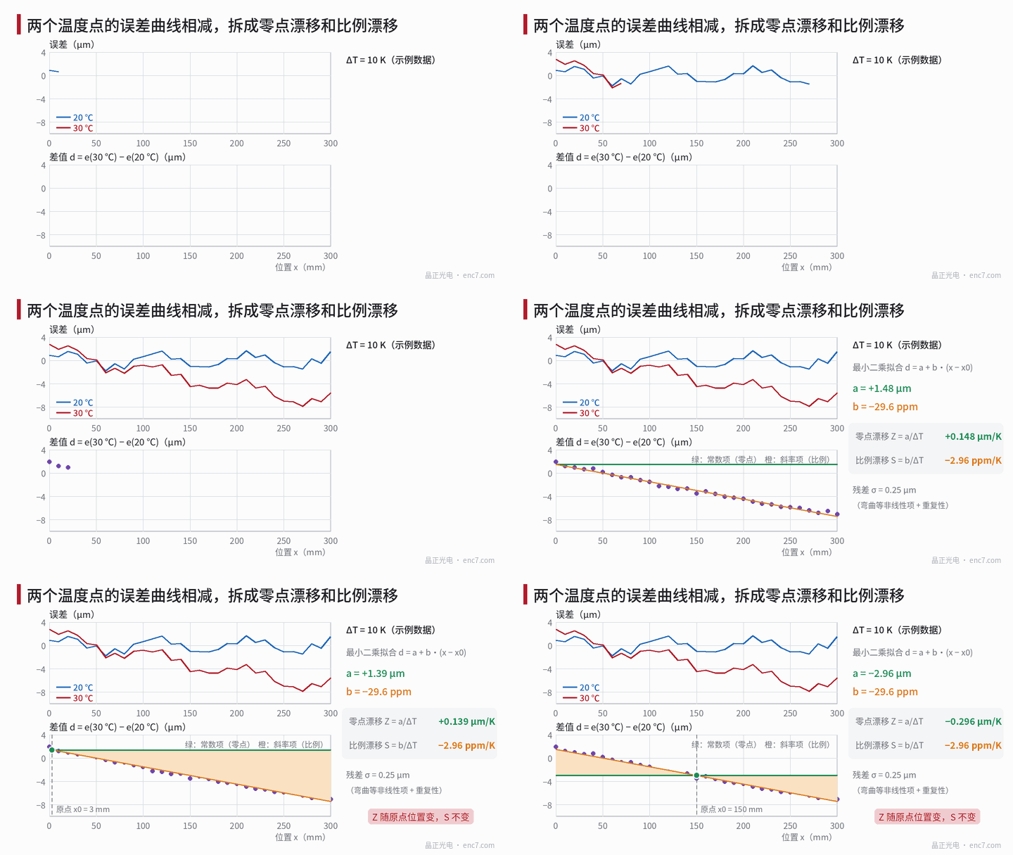
Procedure: soak thoroughly at T1 and at T2, measure the errors e1 and e2 at the same set of positions x_i, in the same direction of travel and with the same reference mark as origin, form the difference d_i = e2 − e1, and fit by least squares
d = a + b·(x − x0)
Then Z = a/ΔT and S = b/ΔT. The residuals reflect nonlinear thermal deformation and repeatability. The standard uncertainty of the slope is
σ_b = σ_r / √Σ(x_i − x̄)²
where σ_r is the residual standard deviation.
Worked example (example data, see Figure 1): one point every 10 mm from 0–300 mm, ΔT = 10 K, the fit gives a = +1.48 μm and b = −29.6 ppm, so Z = +0.148 μm/K and S = −2.96 ppm/K; residual σ_r = 0.25 μm, σ_b ≈ 0.51 ppm, corresponding to an uncertainty in S of about 0.05 ppm/K. At 300 mm the scale term contributes −8.9 μm, 6 times the zero term. Moving the origin to 150 mm changes a to −2.96 μm and Z to −0.296 μm/K.
For a rotary encoder the fit is replaced by a constant plus harmonics:
d(θ) = a + Σ (c_k·cos kθ + s_k·sin kθ)
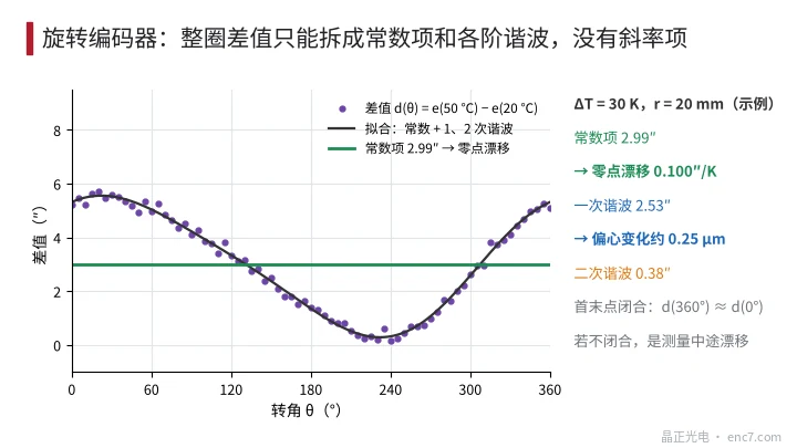
In the example ΔT = 30 K and r = 20 mm, the constant term is 2.99″, so Z = 0.100″/K; the first harmonic is 2.53″, corresponding to an eccentricity change of about 0.25 μm; the second harmonic is 0.38″. If the full-revolution difference does not close from start to end, the reference or the temperature was drifting during the measurement: measure in both directions, or return to the start and remeasure the reference mark. Two temperature points give a secant coefficient; if the coefficient itself varies with temperature, measure at least three temperature points.
Common misjudgements
- Taking the expansion coefficient of the scale material as the “scale drift” without stating whether it is relative to physical length or to the machine; the number can change from −9 ppm/K to +3 ppm/K.
- Reporting zero drift without the origin, or using a fixture that itself drifts with temperature as the reference, so that the result is the combined value of the fixture and the encoder.
- Measuring the amplitude temperature coefficient with constant-light control switched on; the result is then near zero. Measure instead how the LED current changes with temperature, to see how much drive headroom remains at high temperature.
- Reporting the change of a rotary encoder’s first harmonic with temperature as ppm/K; it is in fact a change in eccentricity and the unit should be ″ or μm.
- Not waiting for thermal equilibrium between the two temperature points, so that bending caused by a temperature gradient is taken as a scale term.
Engineering points
- Write the specification as three separate items: Z (″/K or μm/K, stating the origin), S (ppm/K, stating whether the reference is physical length or the machine), and K_A (%/K, stating the LED drive conditions).
- During the test, soak thoroughly at both temperatures, measure in both directions and check start-to-end closure; if a curve is needed, use at least three temperature points.
- Separate the terms by least squares: a straight-line fit a + b·(x − x0) for linear, a constant plus harmonics for rotary; report the residuals as well, and do not force nonlinear terms into S.
- Keep the thermal-expansion path of the readhead bracket short and match its material to the mounting seat: a tangential displacement of 0.07 μm/K at r = 20 mm is already about 0.7″/K.
- Watch the difference between the amplitude temperature coefficients of channels A and B, not only the amplitude itself: a difference of 0.01 %/K produces about 0.4″ of interpolation error after an 80 K rise (2048 lines).
Summary
Zero drift is a shift, scale drift is an expansion or contraction, and the amplitude temperature coefficient is a change in signal strength; the three have different origins and different means of compensation. Least-squares fitting of the error difference at two temperatures can separate the first two, but the zero term depends on the origin, the scale term depends on the reference, and over a full rotary revolution there are only a constant and harmonics — no scale term.
Translated from the ENC7 Chinese technical library (article 0273). Read the Chinese original. Need a disc built to your drawing? Request a quote or see our custom encoder discs.
© Langfang Jingzheng Optoelectronic Technology Co., Ltd. All rights reserved. This article was created with AI assistance.