Selection
Transmissive vs Reflective Encoder Discs: Where Does the Light Go?

A transmissive disc lets light pass through it, so the light source and the detector sit on opposite sides of the disc. A reflective disc sends the light back, so source and detector sit on the same side. The different optical paths place different demands on the substrate, the readhead, the installation space and the surface quality. This article compares the two in one table.
Among optical encoders, some readheads look like a fork that straddles the disc; others are just a small board sitting on one side of it. The difference is the path the light takes: one design lets light pass through the disc, the other has the disc reflect it back.
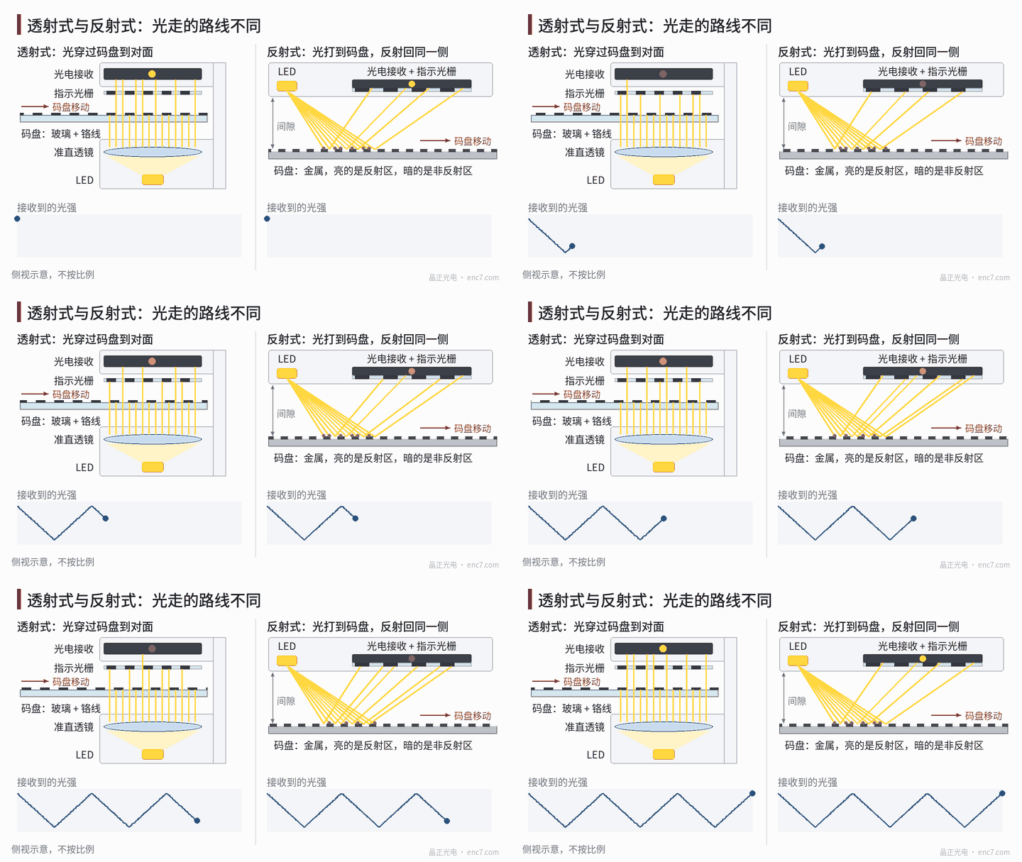
Transmissive: light passes through the disc
In a transmissive design the light source and detector are on opposite sides of the disc. Light from an LED is turned into near-parallel light by a collimating lens and falls on the disc: the lines block light, the gaps transmit it. The light passing through the disc then goes through an index grating and onto the photodetector (Figure 1, left).
The first requirement this places on the substrate is that it must transmit light. Glass discs are the most common, with lines made of chrome deposited on the glass; PC discs also belong to this category. How “black” the lines are is measured by optical density: OD 3, for example, means only 0.1% of the light gets through.
Because the light passes through the whole disc, scratches, stains or bubbles on either surface of the substrate can affect the signal, so both sides must be clean. The readhead needs space on both sides of the disc and is usually fork-shaped, or the source and detector are mounted separately above and below the disc.
Reflective: light comes back
In a reflective design the source and detector are on the same side of the disc, often on the same circuit board. Light strikes the disc at an angle: on a reflective area it is specularly reflected back to the detector; on a non-reflective area it is absorbed or scattered (Figure 1, right).
The substrate does not need to transmit light. Metals such as stainless steel are common, and reflective patterns are also made on glass. What determines signal quality is the difference in reflectance between the reflective and non-reflective areas.
There is an interesting geometric relationship: in the geometric-optics approximation, when a point source and the detector lie in the same plane, the disc pattern reflected onto the detector plane is magnified about 2×. So in a reflective readhead the index grating pitch on the detector is about twice the disc pitch; Figure 1 (right) is drawn this way.
Reflective designs are more demanding of the disc surface. If the reflective surface tilts by an angle, the reflected beam deviates by twice that angle — a 0.1° tilt deflects the beam by 0.2°. Fingerprints and oil films on the surface change the reflectance directly. Flatness, cleanliness and read gap therefore all need to be well controlled.
The two designs compared
| Item | Transmissive | Reflective |
|---|---|---|
| Source and detector | On opposite sides of the disc | On the same side of the disc |
| Disc substrate | Must transmit light: glass, PC | Need not transmit: metal is common, glass also used |
| Pattern contrast comes from | Transmitting vs opaque (optical density) | Reflecting vs non-reflecting (reflectance difference) |
| Readhead | Fork or split, needs space on both sides | One board, single-side mounting |
| Axial size | Relatively large | Easy to make thin |
| Pay special attention to | Both surfaces clean; is the opaque layer dark enough | Surface reflectance, flatness, gap |
Where each is used
Transmissive glass discs offer high accuracy and high line counts and are common in high-resolution servo motor encoders and angle measurement.
Reflective metal discs resist shock and vibration and can be made thin. They suit equipment with tight axial space or heavy vibration, and modular encoders where the disc and readhead are supplied separately and assembled by the user.
These are common pairings, not absolute boundaries. Which one to choose also depends on resolution, installation space, environment and cost; we recommend settling it early in the design together with the disc manufacturer and the readhead solution.
Summary
A transmissive disc lets light pass through, with source and detector on opposite sides, and the substrate must transmit light. A reflective disc returns the light, with source and detector on the same side; it is thinner but more sensitive to the condition of the disc surface. Once you know where the light goes, you know which disc parameters need the closest control.
Translated from the ENC7 Chinese technical library (article 0013). Read the Chinese original. Need a disc built to your drawing? Request a quote or see our custom encoder discs.
© Langfang Jingzheng Optoelectronic Technology Co., Ltd. All rights reserved. This article was created with AI assistance.