Troubleshooting
Troubleshooting: A/B Phase Shifts Whenever the Gap Changes — Magnification Mismatch with Divergent Light
Under point-source illumination the disc shadow is magnified by M = (L + g)/L. A gap change alters M, so detection fields designed for the nominal magnification no longer match the fringes, and the phase difference of A and B fields n periods apart changes by Δφ ≈ 2π·n·Δg/L. This article gives worked examples and gap tolerances, troubleshooting steps, and remedies such as collimation and interleaved arrays.
During alignment the read gap is increased by 20 μm with a shim and the Lissajous figure immediately turns from a circle into a tilted ellipse; on a prototype whose disc has several tens of micrometres of axial runout, the A/B phase difference undulates once per revolution; when the temperature changes, the phase drifts too. If the readhead uses an LED without a collimating lens, or the collimation is poorly adjusted, these phenomena most likely share one cause: under divergent illumination the magnification of the disc shadow on the detection plane changes with the gap, while the detection fields were designed for one particular magnification. This article derives the relation between phase difference and gap and gives tolerance estimates, troubleshooting steps and improvements. The geometry of coplanar reflective layouts is covered in the library article on the geometrical optics of reflective scanning; here the focus is on transmissive designs.
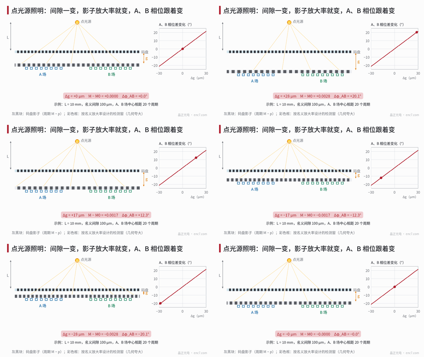
Model: shadow magnification and detection-field phase
A point source sits at distance L from the disc; the detection plane (index grating or detector array) lies a distance g below the disc. A line on the disc at distance x from the foot of the source perpendicular is projected onto the detection plane at M·x, with magnification
M = (L + g) / L
The shadow period is M·p, where p is the disc pitch. The detection fields are designed for M₀ at the nominal gap g₀, with period M₀·p. When the gap becomes g₀ + Δg, ΔM = Δg/L, and the phase offset of the shadow relative to the detection window at distance X from the foot of the source perpendicular on the detection plane is
δφ(X) ≈ −2π · (X / (M₀·p)) · ΔM / M₀
It is proportional to X, so a relative phase appears as soon as two detection fields are not at the same position. With the centres of the A and B fields n shadow periods apart:
Δφ_AB ≈ 2π · n · ΔM / M₀ ≈ 2π · n · Δg / L
Looked at another way, the result is the same: a ray reaching position X on the detection plane has an angle of incidence of about X/L; when the gap changes by Δg, the shadow there shifts laterally by Δg·X/L; for two fields d = n·p apart, the difference in shift Δg·d/L as a fraction of one period is the expression above.
Two further consequences:
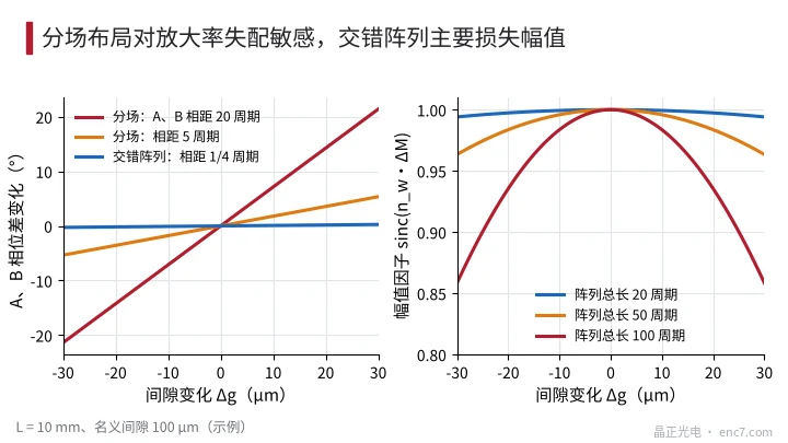
- Amplitude loss within a field. If a detection field contains n_w periods, the phase within the field varies by 2π·n_w·ΔM from one end to the other and the amplitude is multiplied by sinc(n_w·ΔM).
- Common shift. If the detection-field centre is X_c away from the source axis, A and B shift together by about X_c·Δg/L, appearing as a position offset that varies with gap.
Numerical example and gap tolerance
Assumptions: LED without lens, L = 10 mm, nominal gap 0.1 mm, p = 20 μm, centres of the A and B fields 20 periods apart (about 0.4 mm).
| Δg | ΔM | Δφ_AB | Second-harmonic error (2048 lines) |
|---|---|---|---|
| 10 μm | 0.001 | 7.1° | about 6.3″ |
| 20 μm | 0.002 | 14.3° | about 12.5″ |
| 30 μm | 0.003 | 21.4° | about 18.8″ |
The error is taken as half the phase error (in electrical angle); at 2048 lines, 1° of phase difference is about 0.9″. For the same 20 μm gap change, a detection field 50 periods long has an amplitude factor sinc(0.1) ≈ 0.98 — the amplitude is almost unchanged. Magnification mismatch shows up first as phase, not as amplitude. If the detection-field centre is 0.5 mm from the source axis, Δg = 10 μm also causes a common lateral shift of about 0.5 μm, which for a 20 μm pitch corresponds to a zero drift of about 9° electrical.
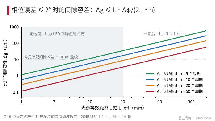
Conversely, for an allowed phase error Δφ_max the gap tolerance is
Δg ≤ L · Δφ_max / (2π · n)
For Δφ_max = 2° (see Figure 2):
| L or L_eff | n = 10 | n = 20 | n = 50 |
|---|---|---|---|
| 5 mm | 2.8 μm | 1.4 μm | 0.56 μm |
| 10 mm | 5.6 μm | 2.8 μm | 1.1 μm |
| 25 mm | 13.9 μm | 6.9 μm | 2.8 μm |
| 250 mm (collimated) | 139 μm | 69 μm | 28 μm |
Without collimation and with separated detection fields, the gap tolerance is only a few micrometres — hard to meet for both assembly and axial runout.
Troubleshooting steps
- Measure the slope of phase versus gap. Move the disc axially, or use shims of uniform thickness to set the gap to g₀ − 10 μm, g₀ and g₀ + 10 μm, and measure the Lissajous phase at each, giving k_φ = dΔφ/dg. If it is roughly linear and the amplitude is essentially unchanged, back-calculate L_eff = 2π·n/k_φ and compare it with the structural dimensions.
- Rule out tilt coupling. Uneven shims also tilt the readhead, and tilt itself changes the phase. Preferably move the disc rather than the readhead, or compare k_φ for both methods.
- Reconcile with axial runout. If the phase undulates once per revolution, record the axial runout curve z(θ) and check whether Δφ(θ) is approximately k_φ·z(θ).
- Check the light source and lens. On readheads with a collimating lens, check the axial position of the LED relative to the focus and whether the lens is mounted backwards or loose; an L_eff far below the design value means the collimation has failed.
- Look at the detection-field layout. Confirm from the readhead documentation whether A and B are in separate fields or interleaved, and whether the array centre is aligned with the source axis.
Remedies
- Collimation. With the LED at the lens focus, the emerging light is approximately parallel. With an axial defocus δ, the equivalent point-source distance is about L_eff ≈ f²/δ; for f = 5 mm and δ = 0.1 mm that is about 250 mm, extending the gap tolerance about 25 times compared with no lens. During alignment, the LED’s axial position can be fine-tuned while measuring k_φ, bringing it close to zero.
- Interleaved array instead of separate fields. With A, B, A− and B− interleaved at quarter-period offsets, the centroids of the phases differ by only a quarter period; magnification mismatch produces almost no relative phase, leaving only the slight amplitude loss sinc(n_w·ΔM) (see Figure 3).
- Symmetrical layout. Make the detector array symmetrical about the source axis so that the common shift cancels on both sides.
- Design the detection period for the actual nominal gap. Use a detection period of M₀·p, with M₀ calculated from the actual nominal gap after assembly, and set gap and axial-runout tolerances by Δg ≤ L·Δφ_max/(2πn).
- Coplanar layout for reflective designs. When the emitting surface of the source and the detection plane are coplanar, the magnification is always 2, independent of the gap.
Engineering notes
- Under divergent illumination the shadow magnification is M = (L + g)/L; each gap change Δg changes the magnification by Δg/L.
- The A/B phase difference changes by Δφ ≈ 2π·n·Δg/L: with L = 10 mm and fields 20 periods apart, a 10 μm gap change shifts the phase by about 7°.
- Magnification mismatch appears first as phase and zero drift with very little amplitude change; a normal amplitude does not rule it out.
- Measuring dΔφ/dg at three gap settings directly yields the equivalent source distance and shows whether the collimation is effective.
- After collimation L_eff ≈ f²/δ, about 250 mm for 0.1 mm defocus and f = 5 mm; during alignment, aim for dΔφ/dg close to zero.
- Prefer interleaved detector arrays symmetrical about the source axis; with separate fields, tighten gap and axial-runout tolerances according to L·Δφ_max/(2πn).
Summary
A/B phase difference changing whenever the gap changes is rooted in the shadow magnification varying with gap under divergent light, while the detection fields are laid out for a fixed magnification. For two detection fields n periods apart, the phase difference changes by about 2π·n·Δg/L, and without collimation the gap tolerance is only a few micrometres. Measuring the phase slope at three gap settings confirms the cause and yields the equivalent source distance; collimation, interleaved arrays and symmetrical layouts are the fundamental remedies, while separate-field designs must tighten gap and axial-runout tolerances accordingly.
Translated from the ENC7 Chinese technical library (article 0230). Read the Chinese original. Need a disc built to your drawing? Request a quote or see our custom encoder discs.
© Langfang Jingzheng Optoelectronic Technology Co., Ltd. All rights reserved. This article was created with AI assistance.