Troubleshooting
Troubleshooting: Amplitude Collapses When the Readhead Moves a Few Tenths of a Millimetre Radially — Track Width Margin

If moving the readhead 0.1 mm radially leaves the amplitude unchanged but another 0.1 mm costs a tenth of it, the detection window has run off the track. This article derives the plateau-plus-linear-drop curve of amplitude versus radial offset and how eccentricity eats into the plateau, explains why the index track fails first, and gives a method and criteria for backing out track width, eccentricity and remaining margin from a radial scan.
A common observation during assembly and alignment: move the readhead 0.1 mm radially and the amplitude hardly changes; move it another 0.1 mm and the amplitude suddenly drops by more than a tenth, the index pulse narrows or is even occasionally lost. Among encoders of the same type, some machines are fine and some have an unstable index. This is not a gradual change of optical sensitivity; the radial edge of the detection window has run off the track and the amplitude falls in proportion to the overlap. This article derives the shape of the amplitude–radial-offset curve, shows how eccentricity eats the plateau and why narrow tracks such as the index track fail first, and then gives a method for measuring the margin with a radial scan. The design formula for track width is in the library article on radial track width; here we only discuss backing out the margin from the symptoms.
Signature of the symptom: plateau plus linear drop
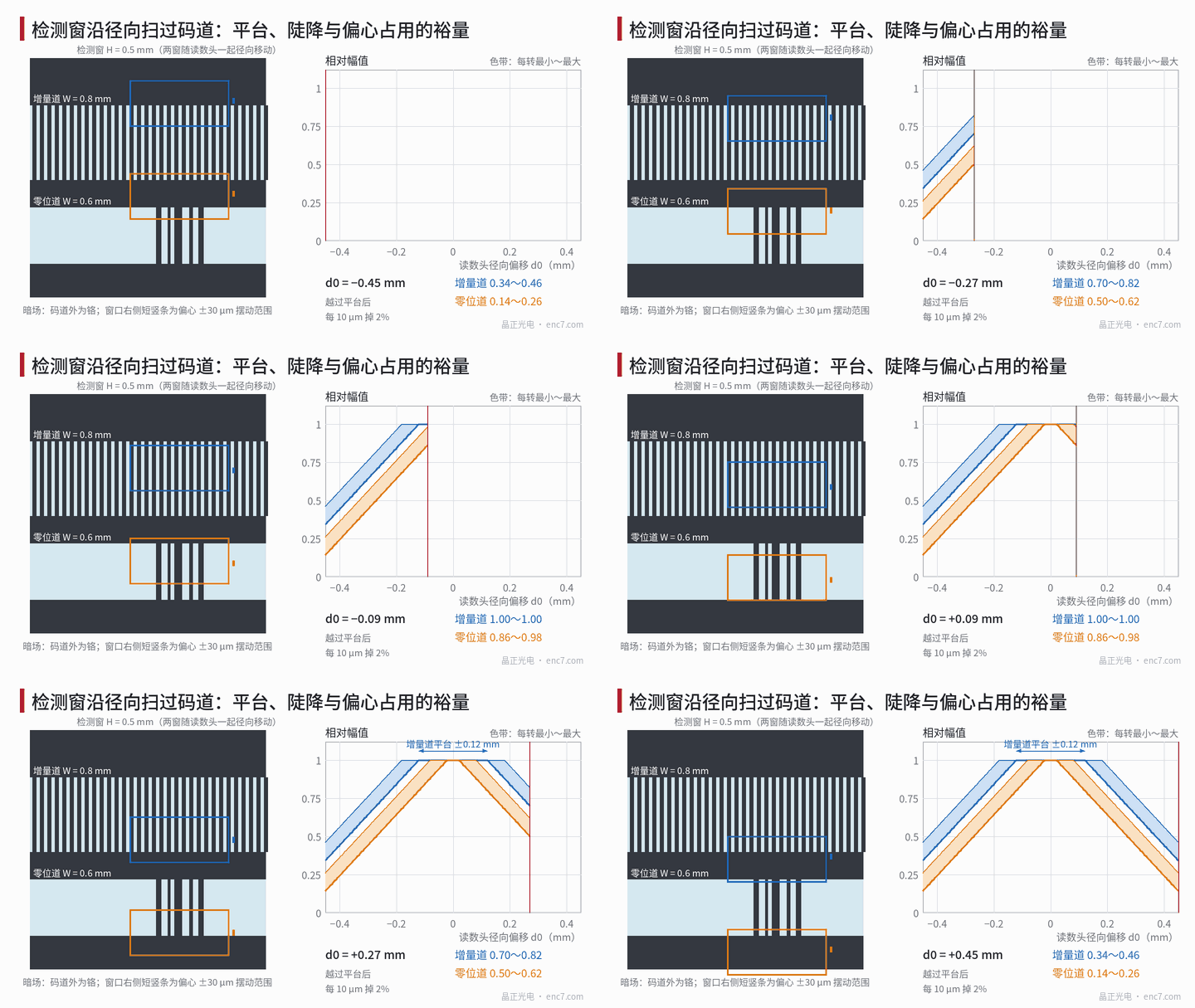
Mount the readhead on a radial micro-positioning stage, run the disc at constant speed and record the amplitude at each step to obtain the amplitude–radial-offset curve. With insufficient track width margin the curve has three features:
- the middle section is flat — moving the readhead does not change the amplitude;
- on both sides of the plateau the amplitude falls approximately linearly, with a slope inversely proportional to the radial height of the window;
- the amplitude undulates within each revolution, more strongly closer to the plateau edge, and not at all in the middle of the plateau.
If the curve is a smooth parabola without a clear plateau, the main cause is more likely pitch mismatch from a read-radius error (see the library article on read radius). The two often coexist: pitch mismatch makes the top of the plateau sag slightly, while running off the track determines the steep drop on both sides.
Model: overlap ratio and eccentricity
Let the track have radial width W, the detection window radial height H (W > H), and the window centre be offset by d from the track centreline. When the area outside the track is chrome (dark field), the part of the window outside the track contributes neither AC nor DC, and the amplitude is proportional to the overlap ratio:
O(d) = [min(W/2, d + H/2) − max(−W/2, d − H/2)] / H
It follows that:
- the plateau half-width is m0 = (W − H)/2; for |d| ≤ m0, O = 1;
- beyond the plateau O = 1 − (|d| − m0)/H; for H = 0.5 mm the loss is 2% per 10 μm;
- the 50% point is at d = ±W/2, independent of H; for |d| ≥ (W + H)/2 the signal disappears.
When the area outside the track is clear glass (bright field), the part outside the track only adds DC; the modulation falls as O/(2 − O), only 0.82 at O = 0.9 — faster than in dark field — and the offset also changes.
Eccentricity e makes the track centreline swing radially at the read point: d(θ) = d0 + e·cos(θ − φ), with d0 the static offset of the readhead. Within one revolution, the plateau half-width for the minimum amplitude shrinks to m0 − e and for the maximum amplitude expands to m0 + e. Eccentricity eats e from each side, leaving only m0 − e for readhead mounting, thermal drift and batch scatter.
Numerical example: why the index track fails first
Example (assumed): incremental track W = 0.8 mm, index track W = 0.6 mm, both detection windows H = 0.5 mm, eccentricity e = 30 μm. The incremental track has m0 = 0.15 mm, the index track only 0.05 mm; after subtracting eccentricity, 0.12 mm and 0.02 mm remain. Relative amplitude within one revolution for a static readhead offset d0:
| d0 (mm) | Incremental track | Index track |
|---|---|---|
| 0 | 1.00 | 1.00 |
| 0.05 | 1.00 | 0.94–1.00 |
| 0.10 | 1.00 | 0.84–0.96 |
| 0.15 | 0.94–1.00 | 0.74–0.86 |
| 0.20 | 0.84–0.96 | 0.64–0.76 |
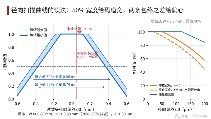
At d0 = 0.1 mm the incremental track is still on its plateau and A and B are perfectly normal, but the index track has already lost 4%–16%. Assume the raw index signal is roughly triangular and the threshold is 50% of the nominal peak; when the peak drops to A times nominal, the Z width becomes 2·(1 − 0.5/A) of nominal: about 81% at A = 0.84, only 44% at A = 0.64, and Z disappears for A ≤ 0.5 (see Figure 2, right). The index appears at only one angle, and which phase of the eccentric swing it falls on differs from unit to unit, so products of the same type behave as “some lose the index, some don’t”. The same applies to fine tracks and commutation tracks of absolute encoders: the narrower the track, the less margin is usually left for it.
If the four detection windows of the readhead are arranged side by side radially (as in some index-grating designs), running off the track first eats the outermost phase, showing up as unequal amplitudes and offset rather than an overall amplitude loss.
Radial scan: backing out the margin from the curve
- Mount the readhead on a radial stage with a micrometer head, or push it with shims of known thickness; run the disc slowly at constant speed, step 10–20 μm at a time, and scan beyond ±(W + H)/2.
- At each step, split by revolutions using Z and record the per-revolution maximum and minimum amplitude of the incremental track, the index track and each absolute track.
- Read the curves (see Figure 2, left): the 50% full width of the maximum curve is W + 2e, that of the minimum curve W − 2e; their mean gives W and a quarter of their difference gives e; the horizontal distance of the 20%–80% section of the mean curve divided by 0.6 gives H; the difference between the plateau centre and the actual mounting position is the mounting offset d_op.
- Calculate the remaining margin m_rem = (W − H)/2 − e − |d_op|. In the example, W = 0.80 mm, H = 0.50 mm, e = 30 μm and d_op = 0.05 mm give m_rem = 70 μm.
The 50% points are used rather than the “start of the plateau” because end transitions and pitch mismatch round the plateau corners, making the knee hard to read, whereas the 50% point barely moves under symmetrical blur.
Criteria: m_rem must cover the temperature-induced relative radial displacement and the assembly scatter of the batch, with some reserve. Running off the incremental track only costs a few percent of amplitude and can be assessed statistically; running off the index track or an absolute track loses pulses or misreads codes and must be assessed worst-case. In the example the index track has only 20 μm left after eccentricity — essentially no room.
Engineering notes
- A plateau followed by a linear drop in the amplitude–radial-offset curve is the signature of the detection window running off the track; the slope is about 1/H, 2% per 10 μm for H = 0.5 mm.
- Subtract the eccentricity e from the plateau half-width (W − H)/2 first; only what remains is usable margin for mounting and thermal drift.
- The index track and absolute tracks are usually the narrowest; scan each track rather than looking only at incremental amplitude.
- Read at the 50% points: the mean of the 50% full widths of the two envelopes gives track width, a quarter of the difference gives eccentricity.
- In dark field, running off the track only reduces amplitude; in bright field it also changes DC, and the modulation falls as O/(2 − O).
- Do a radial scan on the first article, and whenever the readhead type or bracket changes, and record m_rem in the first-article report.
Summary
Amplitude collapsing when the readhead moves a few tenths of a millimetre radially means the detection window has run off the track: amplitude falls with the overlap ratio, the plateau width is W − H, and eccentricity eats e from each side. Narrow tracks such as the index track have the least margin and are first to show a narrowed or lost Z. A radial scan that reads the 50% full widths and slopes of the two envelopes backs out track width, window height, eccentricity and remaining margin, and shows whether to change the bracket location, the centring or the track width.
Translated from the ENC7 Chinese technical library (article 0231). Read the Chinese original. Need a disc built to your drawing? Request a quote or see our custom encoder discs.
© Langfang Jingzheng Optoelectronic Technology Co., Ltd. All rights reserved. This article was created with AI assistance.