Troubleshooting
Troubleshooting: Amplitude Drops at One Fixed Angle — Locating Local Defects and Contamination
If the signal amplitude dips every time the disc reaches the same angle, there is most likely a local defect or stain on the disc. Dip depth is roughly the obscured area divided by the detection window area, and the arc it lasts is roughly the defect length plus the window width. This article gives a method to back-calculate defect size and angular position from oscilloscope readings, the waveform signatures of three defect types, and criteria for acceptable amplitude loss.
The disc turns at constant speed and amplitude is normal at most angles, but at one fixed position it dips for a few degrees, and the dip lines up with the Z pulse every time. This shows the problem is locked to one local area of the disc: a scratch, residual chrome, a particle or a fingerprint. Rather than search the whole disc under a microscope, first calculate the defect’s size, nature and position from the dip on the oscilloscope, then go and check that spot.
Depth and width of the dip
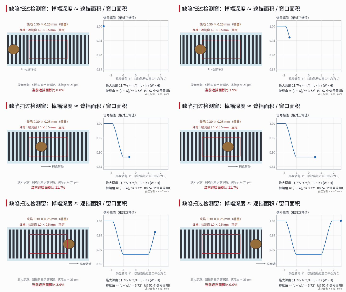
Take single-field reading (all phases interleaved in the same detection window) as the example. When the defect is larger than the pitch, the part of the window it covers no longer produces modulation; all four phases are affected in the same proportion and the A and B amplitudes fall together:
d = A_overlap / (W·H)
where A_overlap is the overlap area of defect and window, and W, H are the window’s tangential width and radial height. With defect tangential length L and radial width h, the arc swept past the window is L + W, and the duration angle is:
Δθ ≈ (L + W) / r
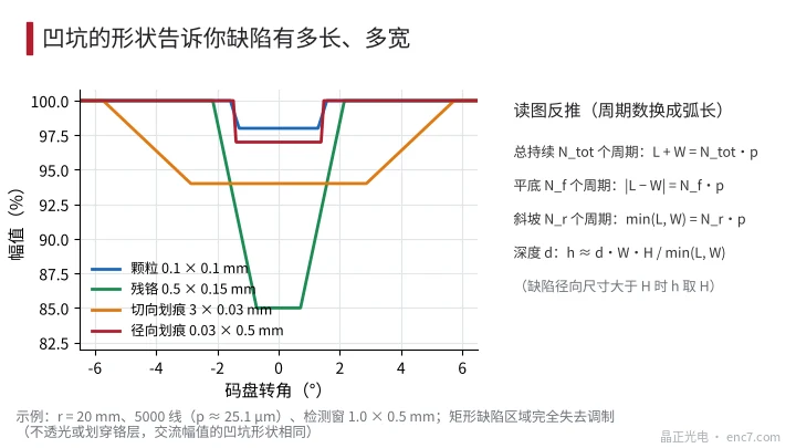
The dip is generally trapezoidal: each side slope takes min(L, W), the flat bottom |L − W|, and maximum depth is min(L, W)·min(h, H)/(W·H); for elliptical defects multiply by about π/4. When the defect is smaller than the pitch, the result depends on whether it lies on a chrome line or a transmitting gap, and a single defect can vary between 0 and about 2×.
Example: r = 20 mm, 5,000 lines (p ≈ 25.1 μm), detection window 1.0 × 0.5 mm (assumed):
| Defect (tangential × radial) | Max depth | Duration | ≈ signal periods | Shape |
|---|---|---|---|---|
| Particle 0.1 × 0.1 mm | 2% | 3.2° | 44 | Narrow slopes, wide flat bottom |
| Residual chrome 0.5 × 0.15 mm | 15% | 4.3° | 60 | Slopes and bottom each ~20 periods |
| Tangential scratch 3 × 0.03 mm | 6% | 11.5° | 159 | Long and shallow |
| Radial scratch 0.03 × 0.5 mm | 3% | 3.0° | 41 | Nearly rectangular, steep edges |
Back-calculating defect size from the oscilloscope
Time readings are affected by speed fluctuation; counting signal periods is more robust. If the dip lasts N_tot periods in total, with N_f in the flat bottom and N_r per side slope, and the pitch is p, then:
L + W = N_tot·p, |L − W| = N_f·p, min(L, W) = N_r·p
If N_r·p is close to the window width W, then L ≥ W and the defect length L = (N_tot − N_r)·p; otherwise L = N_r·p. Then from the depth, the radial size is h ≈ d·W·H/min(L, W). If window illumination is non-uniform the dip edges become rounded; take the slope length as the number of periods between 10% and 90% of depth and extrapolate appropriately.
Angular position: count the periods n_c from the Z pulse to the dip centre; the angle is Δφ = n_c·360°/N. The defect’s position on the disc is Δφ counted from the Z line against the direction of rotation, minus the tangential offset between the Z detector and the incremental window centre shown on the readhead drawing. Under the microscope, turn to that angle using the Z line as reference and search the band r ± H/2 at the read radius; usually it is visible in one field of view.
Waveform signatures of three defect types
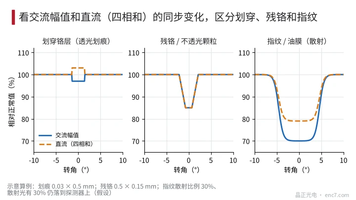
AC amplitude alone cannot tell the nature of a defect; DC must be watched as well. Differential outputs cancel DC, so use the readhead’s single-ended test points or the sum of the four phases (Figure 3):
- Scratch through the chrome: the defect becomes fully transmitting; AC falls by f while DC actually rises, by about f at 50% disc duty cycle. Edges are steep; tangential scratches are long and shallow, radial scratches short and square.
- Residual chrome or opaque particle: AC and DC fall in the same proportion; dip shape follows the defect outline, often a single spot.
- Fingerprint or oil film: mainly scattering. With scattered fraction s, of which η still reaches the detector, AC falls by s and DC only by s·(1 − η) — AC falls more than DC; edges are gradual, duration long, shape irregular, often in patches. The quantitative scattering model is in the library article on contamination.
There is also a look-alike that is not locked to angle: dirt on the readhead window or index grating. It causes constant amplitude loss or offset around the whole revolution, with no fixed phase to Z, and can be distinguished from defects on the disc.
Acceptable amplitude-loss criteria
With single-field reading the dip is a common-mode change in A and B and atan2 interpolation itself produces no error, so the criterion is mainly margin: the minimum amplitude A·(1 − d − η_other) must exceed the alarm threshold with margin, and for square-wave outputs also exceed comparator hysteresis; the relative size of fixed offsets is magnified by 1/(1 − d). Generally d within 10% is not a problem and above 20% should be fixed (example criteria; adjust to the product’s alarm threshold).
With split-field reading (separate windows for A+, B+, A−, B−) it is much stricter: a defect falling in only one field produces an offset of about f/(2M), where M is the modulation. With M = 0.5 and 1% allowed offset (about 1″ for 2,048 lines), the obscured area allowed in a single field is only about 1%.
Note the effect of speed as well: at low speed, automatic gain or self-calibration may follow the dip, “smoothing” it but introducing offset jumps; at high speed the dip lasts only a very short time. Measure at a fixed low speed and disable or record automatic gain.
Engineering notes
- First confirm the dip is locked to Z: locked to the disc means a defect; not locked means check the readhead side.
- Back-calculate size from period counts, not time: L + W = N_tot·p, |L − W| = N_f·p, and depth gives the radial size.
- Watch single-ended DC at the same time: DC rising means scratched-through chrome, proportional fall means an opaque object, AC falling more than DC means scattering contamination.
- For microscope verification, count Δφ from the Z line against the rotation direction and subtract the tangential offset between Z and the incremental window.
- Split-field readheads tolerate local defects far less than single-field interleaved arrays; set incoming-inspection defect size limits separately for each readhead architecture.
- After cleaning, remeasure dip depth at the same angle: shallower means contamination, unchanged means a pattern defect.
Summary
A dip in amplitude at a fixed angle can be used as a ruler: depth corresponds to the share of the window obscured, period count to the sum of defect and window tangential sizes, and Z gives the angular position. Combined with whether single-ended DC rises or falls to judge the defect’s nature, you can go straight to the specified spot on the disc for verification and set acceptable amplitude-loss limits according to the readhead architecture.
Translated from the ENC7 Chinese technical library (article 0204). Read the Chinese original. Need a disc built to your drawing? Request a quote or see our custom encoder discs.
© Langfang Jingzheng Optoelectronic Technology Co., Ltd. All rights reserved. This article was created with AI assistance.