Troubleshooting
Troubleshooting: Amplitude Oscillates Once Every Half Wavelength of Gap Change — Multiple-Beam Interference
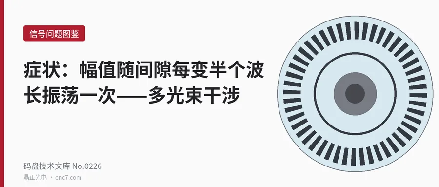
With a very small gap or a narrow-band light source, the surfaces of the disc and the index grating form a low-finesse Fabry–Pérot cavity, and the amplitude oscillates with the gap at a period of λ/2 (0.44 μm at 880 nm). This article derives the oscillation depth 2r/(1+r²) and its decay with coherence length, and gives identification methods such as about 4T/λ fluctuations per revolution, plus countermeasures such as anti-reflection coating and a larger gap.
While adjusting the gap, a strange effect appears: measuring amplitude in 10 μm gap steps gives a curve that jumps up and down, and repeat measurements do not agree. Only a fine scan on a piezo stage reveals that the amplitude oscillates sinusoidally and regularly with the gap, with a period of less than half a micron. Once the disc rotates, the amplitude envelope shows twenty or thirty rapid fluctuations per revolution, unevenly spaced. This is not near-field diffraction but multiple-beam interference between the disc surface and the index grating surface. This article derives its oscillation period and depth, explains why it is usually noticeable only with small gaps or narrow-band sources, and then gives identification methods and countermeasures.
Principle: a low-finesse cavity formed by two surfaces
After passing through the transparent slits of the disc, the light has to cross the air gap g before reaching the index grating. The two facing surfaces have reflectances R₁ and R₂; light bounces back and forth in the gap and the successive transmitted beams add coherently. For monochromatic light at normal incidence the transmittance is the Airy function
T = T₁T₂ / [(1 − r)² + 4r·sin²(2πg/λ)]
where r = √(R₁R₂), T₁ and T₂ are the transmittances of the two surfaces and λ is the wavelength. The transmittance varies with the gap as sin²(2πg/λ), with a period of
Δg = λ/2
which is 0.44 μm at 880 nm. The oscillation depth (peak-to-valley difference divided by peak-to-valley sum) is
V₀ = 2r / (1 + r²)
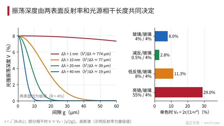
For low reflectance, T ≈ T̄·[1 + V₀·cos(4πg/λ)], i.e. two-beam interference. At normal incidence, the light that passes through a transparent slit of the disc and then through a transparent slit of the index grating normally meets two glass surfaces. Monochromatic oscillation depth for different surface combinations (reflectances are order-of-magnitude values):
| Surface combination | R₁ / R₂ | V₀ |
|---|---|---|
| Glass / glass | 4% / 4% | 8.0% |
| AR coating / glass | 0.5% / 4% | 2.8% |
| Low-reflective chrome / glass | 8% / 4% | 11.3% |
| Bright chrome / glass | approx. 55% / 4% | approx. 29% |
The last row corresponds to a metal reflective disc or a bright chrome face turned towards the reading window; as soon as the cavity reflectance is high, the oscillation becomes much deeper.
Why it usually appears only at small gaps: coherence length
An LED is not monochromatic. Each wavelength oscillates with a slightly different period; the larger the gap, the more the fringes of different wavelengths shift apart, and the superposition smooths the oscillation out. For a Gaussian spectrum the oscillation depth is multiplied by the degree of coherence
V = V₀·|γ(2g)|, |γ(Δ)| = exp[−(π·Δ·Δλ/λ²)² / (4 ln2)]
where Δλ is the spectral FWHM and 2g is the round-trip path difference. The coherence length is l_c = λ²/Δλ, and |γ| falls to one half at a path difference of about 0.44·l_c. For Δλ = 40 nm, l_c ≈ 19 μm:
| Gap g | 2 μm | 5 μm | 10 μm |
|---|---|---|---|
| Degree of coherence | 0.86 | 0.39 | 0.02 |
| Glass/glass oscillation depth | 6.9% | 3.1% | 0.2% |
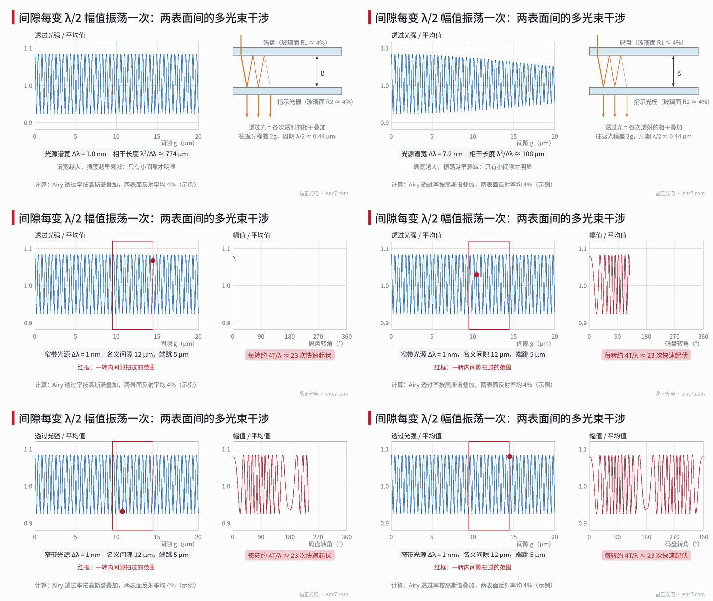
Under ordinary LED illumination the effect therefore appears only in readheads with gaps of a few microns; at the usual gaps of tens to over a hundred microns it is practically invisible. A narrow-band source with 1 nm bandwidth (such as some laser-type sources), however, has l_c of about 0.77 mm, and at a 100 μm gap the degree of coherence is still about 0.8 – almost full-depth oscillation (see Figure 2, left). The divergence of the illumination also smooths the oscillation: at an angle of incidence α the round-trip phase is reduced by 2πgα²/λ; for α = 0.05 rad this only becomes significant at about 180 μm, so for LEDs the spectral effect usually acts first.
Symptoms: four identification criteria
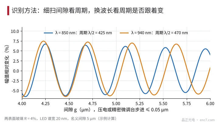
- The period equals λ/2. Scan a 2–3 μm range of gap finely with a piezo stage or precision micro-positioning stage in steps of no more than 0.05 μm: the amplitude oscillates sinusoidally with a period of about 0.44 μm. A coarse scan aliases this into “a rough amplitude–gap curve with poor repeatability”, which is itself a clue.
- The period changes with wavelength. With an LED of a different wavelength the oscillation period changes in proportion to λ: about 425 nm and 470 nm for 850 nm and 940 nm respectively (see Figure 3). The characteristic scale of near-field diffraction is p²/λ, so no such period appears within a micron-scale scan range.
- With axial runout, about 4T/λ rapid fluctuations per revolution. For a peak-to-peak runout T the gap is swept twice per revolution, giving about 4T/λ fluctuations: about 23 at 880 nm and 5 μm runout. The fluctuations are unevenly spaced: densest at the angles where the gap changes fastest, sparsest where the gap reaches its extremes (see Figure 1).
- The modulation depth stays essentially unchanged. Light passing through both surfaces is scaled by the same factor, so the AC amplitude and the DC sum fluctuate together and their ratio is unchanged – unlike near-field diffraction, which changes the modulation depth itself. If the readhead has a DC-sum constant-light loop that is fast enough, the fluctuation moves into the LED current.
As far as interpolation accuracy is concerned, proportional fluctuations of A and B produce no interpolation error; the harm lies in amplitude margin and alarms. But if the disc is tilted and the A and B detection fields are separated along the tilt direction, the gaps of the two fields differ by β·d (β the tilt angle, d the field spacing), the interference phases differ, and unequal amplitudes that vary with angle appear.
Countermeasures
- Increase the gap. With an LED bandwidth of 40 nm and a gap above about 10 μm, the oscillation depth has already dropped to around 0.2%, provided near-field diffraction permits it.
- Anti-reflect the surfaces. An AR coating on the index grating or reading window reduces glass/glass from 8% to about 2.8%; AR on both surfaces brings it down to about 1%.
- Avoid bright face against bright face. If the chrome side of the disc or index grating faces the gap, use low-reflective chrome to avoid forming a high-reflectance cavity.
- Use narrow-band sources with care in imaging-type scanning. Laser-type sources should either be combined with AR coating and a suitable tilt, or a scanning principle that is insensitive to gap should be used instead.
- In principle a tiny wedge angle can average it out. If the gap difference along the length of the detection window reaches λ/2 – for a 2 mm window about 0.22 mrad – the oscillation averages out within the window; this amount is negligible for near-field imaging, but the fixture must control the tilt stably.
Engineering notes
- Amplitude oscillating with gap at a period of λ/2, with the period following a change of wavelength, confirms multiple-beam interference.
- Oscillation depth V₀ = 2r/(1 + r²), r = √(R₁R₂); about 8% for glass/glass and about 29% for bright chrome/glass.
- Under LED illumination it is noticeable only for gaps below about l_c/2 (about 10 μm for 40 nm bandwidth); with narrow-band sources it also appears at common gaps.
- With runout T there are about 4T/λ unevenly spaced rapid fluctuations per revolution, which can be used directly as a check.
- AC and DC fluctuating in step with unchanged modulation depth is a simple criterion for distinguishing it from near-field diffraction.
- Countermeasures in order of cost: increase the gap, AR coating, low-reflective chrome, change the light source.
Summary
Amplitude oscillating once for every half-wavelength change in gap is the work of a low-finesse cavity formed by the surfaces of the disc and the index grating. The oscillation depth is set by the reflectances of the two surfaces and is attenuated with gap by the coherence length of the source, so under LED illumination it is mostly seen at small gaps of a few microns, while narrow-band sources show it at common gaps too. Fine gap scanning, changing the wavelength and counting the fluctuations under runout confirm it; a larger gap, AR coating and low-reflective chrome are the main countermeasures.
Translated from the ENC7 Chinese technical library (article 0226). Read the Chinese original. Need a disc built to your drawing? Request a quote or see our custom encoder discs.
© Langfang Jingzheng Optoelectronic Technology Co., Ltd. All rights reserved. This article was created with AI assistance.