Troubleshooting
Troubleshooting: Amplitude Undulates Twice per Revolution — Disc Saddle Warp and Shaft Ellipticity
An amplitude envelope that undulates twice per revolution usually means the read gap contains a cos2θ component: disc saddle warp reaches the read radius as F·(r/R)², and quadratic deformation of the hub face is lever-amplified about 4×. This article gives the conversion from surface form to amplitude drop, flatness criteria, and separation methods comparing free and clamped states and re-mounting at 90°.
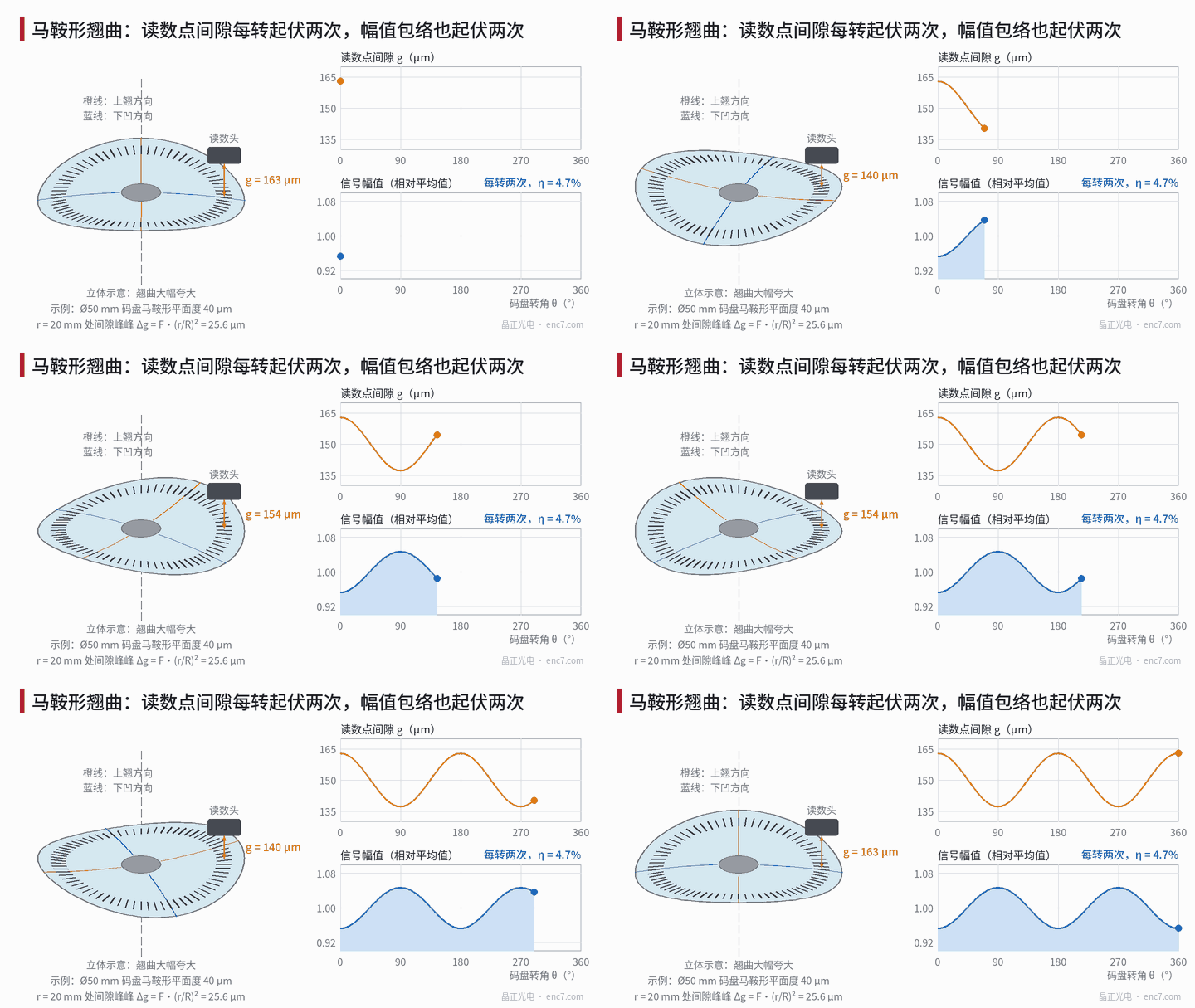
After Z-triggered multi-revolution synchronous averaging, the A and B envelopes undulate twice per revolution and the Lissajous circle expands and contracts twice in one turn. Axial runout and eccentricity give once-per-revolution variation (see the previous article in this series); twice means the gap or radial position at the read point contains a cos2θ component — some part that rotates with the disc has twofold symmetry. This article first writes out the conversion from saddle warp to amplitude drop, then discusses hub and shaft contributions, and finally gives criteria and separation measurements.
Conversion from saddle warp to amplitude drop
A saddle is the most common quadratic form of a thin plate:
z = a·r²·cos2θ
It is bending with equal curvatures of opposite sign in two directions, often from anisotropic film stress, rolling residual stress in thin metal sheet, or uneven cooling. Within outer radius R, flatness by the minimum-zone method is F = 2aR² (by symmetry the two enclosing planes are horizontal). Peak-to-peak gap at read radius r_h is:
Δg = 2a·r_h² = F·(r_h/R)²
With the imaging-read amplitude–gap curve (relative slope S = (1/m)·dm/dg), the 2×/rev fluctuation ratio is:
η ≈ |S|·Δg/2
Example: Ø50 mm disc, r_h = 20 mm, λ = 0.88 μm, illumination angular width 20 mrad (assumed).
| Saddle flatness F | Δg | 5,000 lines, g0 = 150 μm (S ≈ −0.37%/μm) | 10,000 lines, g0 = 25 μm (S ≈ −0.84%/μm) |
|---|---|---|---|
| 10 μm | 6.4 μm | η ≈ 1.2% | η ≈ 2.7% |
| 40 μm (thin sheet) | 25.6 μm | η ≈ 4.7% | η ≈ 10.9% |
Bowl warp z = c·r² is axisymmetric: it only changes the nominal gap and produces no undulation; tilt gives once per revolution. So the number on a flatness report cannot be converted to undulation directly — decompose the form and take only the cos2θ term.
2nd-order contributions from hub and shaft
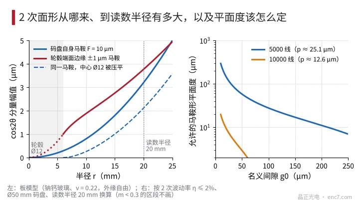
Quadratic deformation of the hub face is amplified. Two-point clamping in turning, an open hub locked by one screw, or a hollow shaft pressed by a clamp ring can all make the mounting face a saddle. Once the disc sits against that face, the inner edge follows both the height and the slope of the face, and the outer edge lever-amplifies the undulation. Kirchhoff annular-plate calculation (inner edge follows the face, outer free): hub Ø12 mm, saddle ±1 μm at the face edge becomes about ±3.8 μm at r = 20 mm, gain G ≈ 3.8; rigid tangent extrapolation would give 5.7, and plate bending removes some of that. The ratio is set by geometry alone, independent of disc thickness and material.
Clamping flat removes only part of the warp. Conversely, if the disc itself has a saddle and the hub forces the central Ø12 mm flat, about 66% of the saddle component remains at the read radius; forcing Ø16 mm flat leaves about 49%. Adhesive bonding generally fills gaps with the adhesive layer and does not flatten the disc, so warp is essentially retained as-is.
Ellipticity: distinguish rotating and stationary parts. A hollow shaft, hub bore or bearing inner ring pressed into an ellipse produces 2× radial runout synchronous with angle under constant radial load, and may deform the mounting flange with it. A housing pressed elliptical is stationary: it mainly changes clearance and preload; the resulting runout usually tracks cage speed rather than angle strictly, and is weakened by Z-synchronous averaging. Twice-per-revolution radial runout affects amplitude noticeably only when track-width margin is insufficient — the same mechanism as eccentricity going out of bounds.
Turning flatness into criteria
Given an allowed 2×/rev fluctuation η_a, the allowed peak-to-peak gap at the read radius and the disc saddle flatness are:
Δg_a = 2η_a/|S|, F_a = Δg_a·(R/r_h)²
With η_a = 2%, Ø50 mm, r_h = 20 mm:
| Read condition | Δg_a | Disc saddle flatness F_a | Hub-face quadratic undulation (peak-to-valley, G ≈ 3.8) |
|---|---|---|---|
| 5,000 lines, g0 = 150 μm | 10.8 μm | 16.9 μm | 2.9 μm |
| 10,000 lines, g0 = 25 μm | 4.8 μm | 7.4 μm | 1.3 μm |
Drawing flatness includes bowl and other non-undulating components, so using it as a hard limit is conservative; a more direct acceptance quantity is the 2× component of axial runout at the read radius after assembly. The hub-face column shows that at fine pitch the face’s quadratic undulation must be controlled to the micrometre level — far tighter than the disc itself.
Free-state vs clamped-state comparison
- Free state: rest the disc on three supports at the same radius, 120° apart; measure form with an interferometer or laser scan and fit the saddle coefficient a and its azimuth. Self-weight sag on three supports contains only axisymmetric and 3rd/6th-order components and does not mix into cos2θ.
- Clamped state: mount on hub and shaft; with Z as reference measure axial runout at r = 15 mm and 20 mm, take amplitude and phase of the 2× component. Disc self-warp grows as r², so the two-radius ratio is about 1.78; deformation transmitted from the hub face grows more slowly, about 1.37 for the same geometry.
- Log: if the clamped 2× component is close to a·r_h² and its azimuth matches the free-state mark, the problem is the disc; if it grows markedly after clamping or varies with clamp force, the problem is the hub and clamping method.
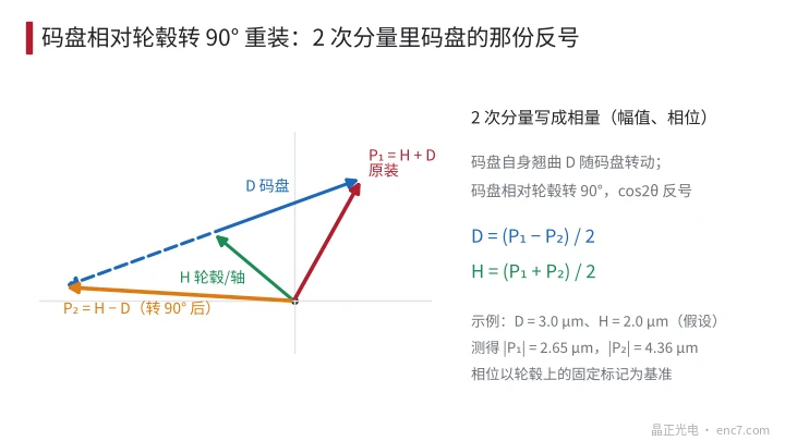
- Re-mount at 90°: for demountable clamping, rotate the disc 90° relative to the hub and re-mount. The disc’s own cos2θ reverses sign; with a fixed mark on the hub as phase reference, the two measured phasors are P₁ = H + D, P₂ = H − D, so D = (P₁ − P₂)/2, H = (P₁ + P₂)/2 (Figure 3).
- Back to the signal: predict η from the 2× component and the measured slope S, and compare with the measured envelope; only when they agree is the main cause identified.
Engineering notes
- For 2×/rev envelope undulation, first check whether it is strictly synchronous with Z: if yes, look for twofold symmetry on rotating parts; if not, check bearings and housing.
- Only the cos2θ term of flatness causes 2× undulation; the conversion is Δg = F·(r_h/R)², and the farther out the read radius the more sensitive.
- Quadratic hub-face deformation is lever-amplified about 3–4× to the read radius; at fine pitch keep face quadratic undulation within 1–3 μm.
- Avoid two-point clamping and single-screw open clamps near the disc mounting face; when clamping is needed, keep the clamp away from the face or use a full-circle distributed structure.
- Free-state form on three supports avoids self-weight interference and yields the saddle coefficient directly.
- On demountable structures, 90° re-mount separates disc and hub contributions more cheaply than swapping parts repeatedly.
Summary
Amplitude undulating twice per revolution means the read gap contains a cos2θ component. Disc saddle warp reaches the read radius as F·(r_h/R)²; quadratic hub-face deformation is lever-amplified and often matters more than the disc itself. Convert flatness into criteria for both, then separate sources by free vs clamped comparison and 90° re-mount to decide whether to change the disc or the clamping.
Translated from the ENC7 Chinese technical library (article 0202). Read the Chinese original. Need a disc built to your drawing? Request a quote or see our custom encoder discs.
© Langfang Jingzheng Optoelectronic Technology Co., Ltd. All rights reserved. This article was created with AI assistance.