Troubleshooting
Troubleshooting: Amplitude Undulation Count Equals Screw Count — Clamping Deformation
When envelope undulations per revolution equal the number of clamp screws, the cause is usually an n-lobe ripple from point loading by the clamp ring. This article estimates ripple versus torque with an annular thin-plate point-load model (example: 3 M2 screws at 0.15 N·m ≈ 3.8 μm, 4 screws ≈ 1.4 μm), and gives spectrum identification, stepped-torque retest and criteria for switching to adhesive bonding.
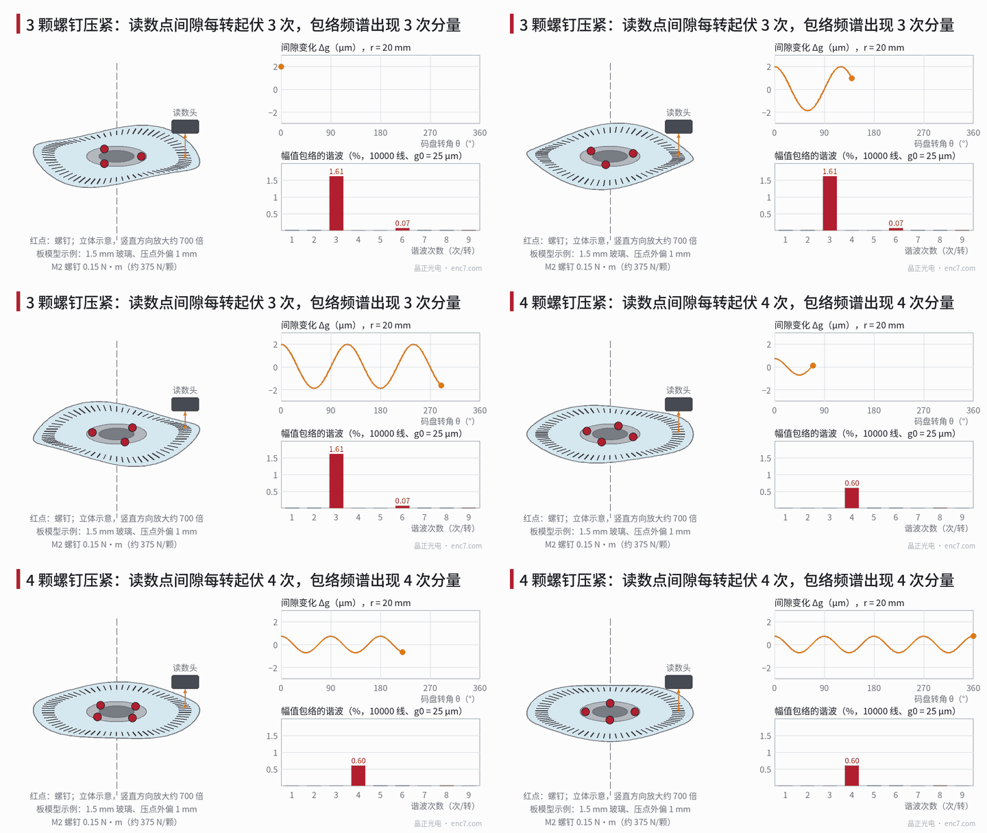
A disc held on the hub by a clamp ring and 3 screws shows A/B envelopes undulating 3 times per revolution on the scope; change to a 4-screw design and the undulation becomes 4 times. The count follows the screw count, so the read-point gap contains a cos(nθ) component from n concentrated clamp forces pressing an n-lobe ripple into the disc. This article quantifies the mechanism: how large the ripple is, how it relates to torque, how to recognise it in the envelope spectrum, and when to abandon screw clamping.
Model: n point loads press an n-lobe ripple
Example model (assumed): soda-lime glass disc 1.5 mm thick, outer radius 25 mm, inner edge supported at the hub-step outer edge a = 7 mm (treated as clamped); clamp-ring pressure points sit a further c = 1 mm outboard of the step; the ring is soft, so the force F of each of n screws acts approximately as a concentrated load at the pressure point. This is an upper-bound point-load case.
n equally spaced point loads expand as a Fourier series along the circumference containing only orders 0, n, 2n, …:
q(θ) = (nF/(2π·r_s))·[1 + 2·Σ cos(knθ)]
where r_s = a + c. The 0th-order term presses the disc into a uniform dish and only changes the nominal gap; the cos(nθ) term produces the n-lobe ripple. Each term has an analytical Kirchhoff annular-plate solution (inner edge clamped, outer free, line load at r_s); superposition gives the gap undulation at read radius r_h = 20 mm.
Preload per screw from torque:
F = T / (K·d)
K is the torque coefficient (≈ 0.2 for dry steel threads), d the nominal thread diameter. An M2 screw at 0.15 N·m gives F ≈ 375 N.
How large is the ripple
Peak-to-peak n-lobe ripple at the read radius from the model above:
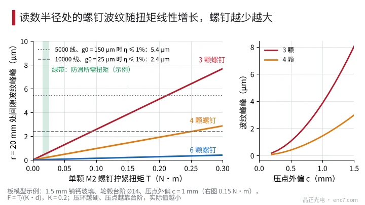
| Screw count | Per 100 N (c = 1 mm) | Per 100 N (c = 0.5 mm) | M2, 0.15 N·m (c = 1 mm) |
|---|---|---|---|
| 3 | 1.02 μm | 0.28 μm | 3.8 μm |
| 4 | 0.38 μm | 0.11 μm | 1.4 μm |
| 6 | 0.05 μm | 0.02 μm | 0.2 μm |
Direct rules: ripple is proportional to torque; increasing pressure-point offset c from 0.5 mm to 1 mm multiplies ripple by about 3.7×, roughly as c²; going from 3 to 4 screws drops ripple to about 0.37×, and to 6 screws to about 5%, because higher-order ripple decays faster in the plate; for fixed geometry ripple is inversely proportional to plate bending stiffness D = E·t³/(12(1 − ν²)), so under the same torque a 0.3 mm stainless sheet ripples more than an order of magnitude above a 1.5 mm glass disc. A stiffer ring and pressure points closer to the step approach uniform line load and reduce the actual value.
In signal terms: at 10,000 lines, r = 20 mm (p ≈ 12.6 μm), nominal gap 25 μm, λ = 0.88 μm, the 3.8 μm ripple from 3 screws produces about 1.6% of 3rd-order envelope component, and 4 screws about 0.6% (Figure 1). Capping η ≤ 1%, allowable peak-to-peak ripple is about 2.4 μm in that condition, versus about 5.4 μm at 5,000 lines, g0 = 150 μm (Figure 2).
Recognising it in the envelope spectrum
- Order: after Z-triggered multi-revolution synchronous averaging, FFT the envelope. With equal torque only orders n, 2n, … appear, and 2n is much smaller than n.
- Phase: mark each screw’s angular position relative to Z; extrema of the n-th component should align with a screw or midway between screws (depending on whether the readhead is on the same side of the ring or opposite). An n-th component that does not align with screws needs another n-fold source — chuck marks from hub turning, adhesive dots, etc.
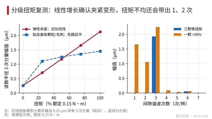
- Uneven torque as corroboration: when one of 3 screws is 50% higher than the other two, the plate model gives read-radius gap harmonics of about 1.7 μm (1×), 1.1 μm (2×) and 2.2 μm (3×) amplitude. Uneven torque turns part of the n-lobe ripple into once-per-revolution “axial runout”, easily misread as tilt (Figure 3).
Stepped-torque retest
Loosen all screws, then tighten diagonally in steps: zero, 1/4, 1/2, 3/4 and full rated torque; at each step record amplitude and phase of the n-th component of axial runout (or envelope) at the read radius; finally loosen and retighten once for repeatability.
- Nearly linear, stable phase: elastic clamp deformation; the zero-torque intercept is pre-existing n-th-order form of disc or hub. The slope is the structure’s torque–ripple coefficient and can set the torque directly.
- Jump at low torque, then flat: particles, burrs or an uneven step face under a pressure point — contact beds in first, then elastic deformation; clean and check step-face flatness first.
- Phase rotates with torque, large difference between retightens: multiple sources stacked or unstable contact; the screw-clamp scheme itself is unreliable.
When to switch to adhesive or distributed clamping
First compute the clamp force actually needed against slip. Example: Ø50 mm × 1.5 mm glass disc, bore Ø8 mm, mass ≈ 7.2 g, inertia ≈ 2.3×10⁻⁶ kg·m². At max angular acceleration 5×10⁴ rad/s², inertial torque ≈ 0.115 N·m; with friction coefficient 0.15 and friction radius 8 mm, total clamp force needed ≈ 96 N; safety factor 2 gives ≈ 64 N per screw, about 0.026 N·m on an M2 — roughly one-sixth of common torque. Ripple from 3 screws is then about 0.65 μm.
Three cases follow:
- Ripple still over budget at the force needed against slip: point-screw clamping fails — switch to adhesive, or to a hard ring with 6+ screws, pressure points on the step (c ≈ 0), and a soft pad for distributed clamping.
- Over budget at rated torque, OK at the force needed against slip: reduce torque, add thread locking, and retest after thermal cycling and vibration to confirm no slip or loosening.
- Stepped retest nonlinear or poor repeatability (difference between tightenings over about 30% of budget): do not try to tune torque — change the structure.
Engineering notes
- Envelope undulation count equal to screw count and phase aligned with screws essentially locks in clamping deformation.
- Screw ripple is proportional to torque, roughly to c², and inversely to plate bending stiffness; aligning pressure points with the support step is the cheapest fix.
- At the same total clamp force, more screws mean less ripple: in the example 4 screws ≈ 0.37× of 3, and 6 only about 5%.
- Set torque from anti-slip need, not from screw strength; glass discs often need far less clamp force than common torque.
- Tighten diagonally in steps; uneven torque turns part of the n-lobe ripple into once-per-revolution undulation.
- Point loading also produces n-th-order in-plane disc deformation and n-th-order angle error — include that in the assessment.
Summary
Undulation count equal to screw count is the n-lobe ripple left by clamp-ring point loads on the disc. An annular-plate point-load model estimates ripple versus torque, pressure-point location and screw count; envelope spectrum order and phase identify it; stepped-torque retest confirms it. When ripple at the anti-slip clamp force still exceeds budget, or retest is nonlinear or non-repeatable, switch to adhesive or distributed clamping.
Translated from the ENC7 Chinese technical library (article 0203). Read the Chinese original. Need a disc built to your drawing? Request a quote or see our custom encoder discs.
© Langfang Jingzheng Optoelectronic Technology Co., Ltd. All rights reserved. This article was created with AI assistance.