Troubleshooting
Troubleshooting: Count Toggles Between Two Values When Stopped — Hysteresis and Micro-Vibration
Stopped near an edge, noise or micro-vibration makes the comparator cross the threshold repeatedly and the count toggles between two values. This article gives a hysteresis criterion from the Rice formula (H ≈ 15σ_v at 1 MHz bandwidth), estimates micro-vibration with ΔV ≈ A·2π·x_v/p, explains the cost of the hysteresis dead band, and the troubleshooting order of disabling the drive, locking the shaft and then adding hysteresis.
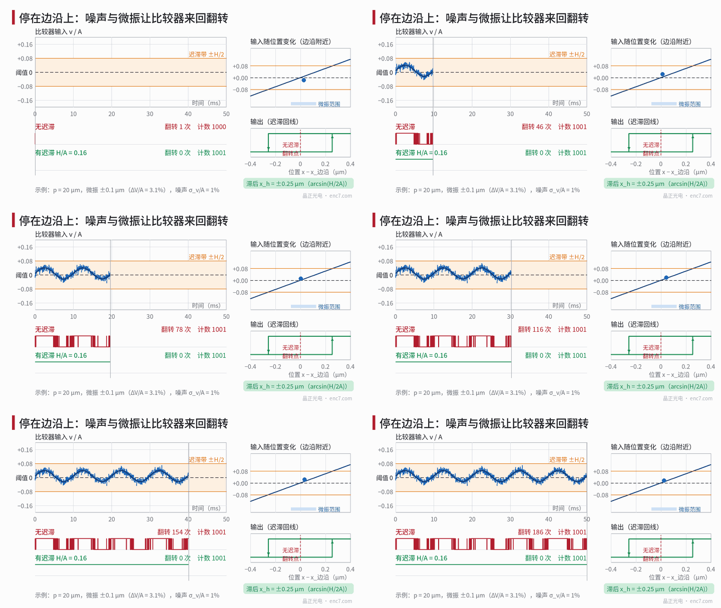
The motor has stopped, yet the host position toggles between 1000 and 1001 — sometimes once every few seconds, sometimes too fast to count; stop elsewhere and it does not toggle at all. This is stop-count chatter: the shaft sits near an A or B edge, the comparator input wanders across the threshold, and the output flips repeatedly. The cause may be electrical noise or genuine shaft motion (servo-hold dither, machine-structure vibration); the fixes differ sharply. This article first derives quantitative criteria for both, then the cost of hysteresis, and finally a field troubleshooting order.
What happens when stopped on an edge
Suppose the shaft stops a distance d from an A-phase edge. Near the edge the sine is approximately linear, so the comparator input is
v ≈ A·2π·(d + x_v·sin2πf_v t)/p + n(t)
with A signal amplitude, p pitch, x_v mechanical micro-vibration amplitude, n(t) electrical noise (rms σ_v). Voltage noise referred to position is
σ_x = p·σ_v / (2πA)
Example: p = 20 μm, A = 0.5 V, σ_v = 2 mV (σ_v/A = 0.4%) → σ_x ≈ 12.7 nm. Without hysteresis, any stop within about 5σ_x of the edge (±66 nm) flips more than once per second by the crossing-rate formula below. With 4 edges per signal period, random stops hit chatter at about 4 × 0.13 / 20 ≈ 2.6% of positions — exactly why “stop elsewhere and it does not toggle”.
In ×4 decode, B stays put while A flips back and forth, so the count alternates +1/−1 with no net accumulation. That differs from permanent under-count from reversed edge order (see the count-reversal article in this series).
Criterion 1: hysteresis must cover the long-term noise peak
With symmetric hysteresis total width H, the rising trip is H/2 above threshold and the falling trip H/2 below. Worst case is the signal parked in the middle of the band, when every flip needs noise to punch out by H/2. For Gaussian white noise of bandwidth B, the Rice mean crossing rate of level u is
ν = (B/√3)·exp(−u² / 2σ_v²)
With u = H/2, B = 1 MHz:
| H/2 | Flips per hour |
|---|---|
| 5σ_v | ≈ 7.8×10³ |
| 6σ_v | ≈ 32 |
| 7σ_v | ≈ 0.05 |
| 7.5σ_v | ≈ 1.3×10⁻³ |
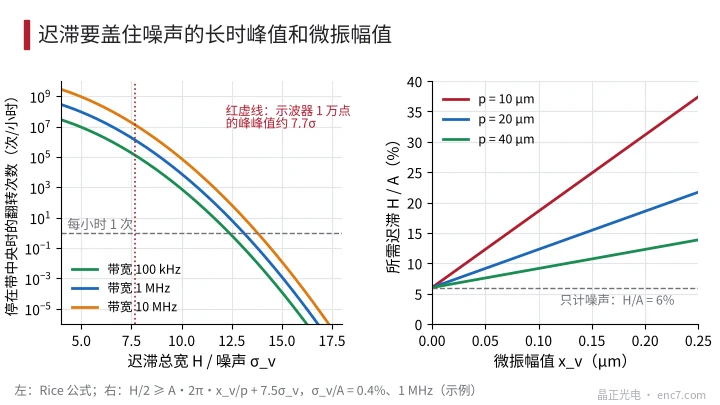
So “hysteresis greater than noise peak-to-peak” must be read statistically over long time. Peak-to-peak seen on one scope screen of 10,000 points is about 7.7σ_v; H only slightly larger still allows tens of flips per hour when parked mid-band. For ≤ 10⁻³ flips/hour at 1 MHz, H ≈ 15σ_v; at 100 kHz about 14σ_v (Figure 2 left). Bandwidth barely matters; H/σ_v does.
Criterion 2: micro-vibration voltage swing must stay under H/2
When the shaft truly moves, micro-vibration at the comparator input is
ΔV ≈ A·2π·x_v / p
At p = 20 μm, 0.1 μm of micro-vibration is already 3.1% of amplitude; at p = 10 μm it doubles. No-flip requires micro-vibration swing plus noise margin still inside the band:
H/2 ≥ A·2π·x_v/p + k·σ_v
with k ≈ 7.5 from above. Noise alone needs H/A ≈ 6%; add 0.1 μm micro-vibration and about 12.3% is required (Figure 2 right). Finer pitch sees the same micro-vibration more easily.
One principle first: if the shaft is truly moving, the encoder following ±1 count is correct measurement; adding hysteresis only hides real motion in a dead band. Use hysteresis to cover it only when that motion is harmless to the system but count chatter triggers alarms or display flicker.
Cost of hysteresis: position lag and bidirectional dead band
Hysteresis delays every edge. With normalised hysteresis h = H/(2A), rising and falling edges each lag by
φ_h = arcsin(h) (electrical angle)
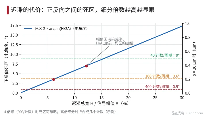
The gap between forward and reverse trip points is 2φ_h — a dead band — or 2φ_h·p/(2π) in displacement. At H/A = 6% the dead band is about 3.4° (≈ 0.19 μm at p = 20 μm); at H/A = 12.3% about 7.0° (≈ 0.39 μm).
Under ×4 square-wave output (90° per count) that dead band is almost invisible; under interpolated output it is not: at 100 counts/period, 7.0° ≈ 2 counts; at 400 counts/period ≈ 8 counts — clear “lost motion” on reversal (Figure 3). Another easily missed point is amplitude: H is set in volts, so when disc contamination or gap growth halves A, h doubles and so roughly does the dead band. Size hysteresis for minimum working amplitude and keep H ≪ 2A_min by design.
Troubleshooting order: first decide whether the shaft is really moving
- Watch the flip rhythm. Scope the A square wave, or log count versus time. Random, clustered, short-interval flips → mostly electrical noise; periodic flips whose frequency matches the servo loop or structure → real motion.
- Disable the drive. With safety assured (vertical axes braked or supported first), turn servo enable off. If chatter stops, the position loop is hunting ±1 count — a control problem: retune gains/integral or set a position dead band in the controller, not the encoder.
- Lock the shaft. Clamp or brake the shaft and stop nearby vibration sources. Chatter gone → structural vibration transmitted as real displacement; chatter remains → electrical noise.
- Measure noise. Turn slowly to a chattering position; measure σ_v and amplitude A within system bandwidth at the comparator input (or differential test point). Check existing hysteresis against H/2 ≥ 7.5σ_v; if noise has spikes synchronous with motor PWM, fix grounding and shielding first.
- Add hysteresis or narrow bandwidth. Choose H from both criteria, then convert the dead band to counts; bandwidth only needs to cover max signal frequency N·n/60 with margin — wider only adds noise.
Engineering notes
- Stop-count chatter appears only near edges; at σ_v/A = 0.4%, p = 20 μm about 2.6% of stop positions hit it — reproducing at another position is step one.
- Design hysteresis for the long-term peak: at 1 MHz, under 10⁻³ flips/hour, H ≈ 15σ_v — about 2× the peak-to-peak seen on a scope.
- Micro-vibration criterion: A·2π·x_v/p + 7.5σ_v ≤ H/2; at 20 μm pitch, 0.1 μm micro-vibration is already ~3% of amplitude.
- Hysteresis dead band = 2·arcsin(H/2A); at high interpolation convert to counts, and compute at minimum amplitude.
- Disable drive first, then lock the shaft, and only then touch the circuit: servo hunting and structural vibration are real motion and should not be masked by hysteresis.
- Narrowing bandwidth and improving grounding reduce σ_v at lower cost than simply raising hysteresis.
Summary
Count toggling between two values when stopped is the signal parked near an edge with noise or micro-vibration driving the comparator across threshold repeatedly. Hysteresis must cover both the long-term noise peak and the micro-vibration swing, but it costs a dead band of 2·arcsin(H/2A), conspicuous at high interpolation and low amplitude. In the field, disable the drive and lock the shaft to decide whether the shaft is really moving, then set hysteresis from σ_v or reduce noise.
Translated from the ENC7 Chinese technical library (article 0221). Read the Chinese original. Need a disc built to your drawing? Request a quote or see our custom encoder discs.
© Langfang Jingzheng Optoelectronic Technology Co., Ltd. All rights reserved. This article was created with AI assistance.