Troubleshooting
Troubleshooting: Equally Spaced Undulations in the Error Curve — Telling Mask Stitching, Adhesive Dots and Screws Apart
When the error curve shows n equally spaced undulations per revolution, the shape points to the source: sector stitching of the photomask gives steps with harmonics falling as 1/k; local stress at adhesive dots gives bumps with harmonics cut off quickly; screw clamping is nearly sinusoidal and dominated by the n-th order. This article derives the harmonic signatures of all three and gives a separation procedure using the first difference, a changed mounting angle and stress-relief re-measurement.
The full-circle error is calibrated against a reference encoder, and the curve shows n equally spaced undulations per revolution: 4, 6 or 8. Sources with n-fold symmetry are few, and the three most common are: a photomask stitched together from n sectors, a disc bonded with n adhesive dots, and a clamp ring tightened with n screws. All three may produce an n-th harmonic of the same size, yet the remedies are completely different: stitching goes back to the mask process, adhesive dots need a changed bonding process, screws need a changed clamping method. The stitching process itself is covered in the photolithography articles of this library and the effect of screws on amplitude in the screw-count article of this series; this article only discusses how to separate the three from the error curve.
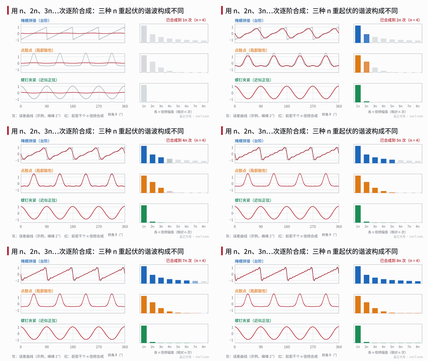
Curve shapes of the three sources
Mask stitching: steps. With large photomasks or step-and-repeat writing, the full-circle pattern is assembled from n sector fields. Every field has the same angular scale or rotation error, so the error within each field is the same ramp; placement errors between fields form steps at the boundaries. The readhead averages over the few dozen periods in its window, so on the curve a step appears as a steep slope as wide as the angular width of the window: a 0.5 mm window at r = 20 mm is about 1.4°.
Adhesive dots: local bumps. Cure shrinkage and thermal mismatch of each adhesive dot cause local in-plane distortion and out-of-plane undulation near the dot; the angular error forms a bump near each dot (with left–right symmetric loading it can also be an S shape with one positive and one negative lobe). Its width is set by the dot size and its distance from the read radius; the curve is smooth, without steps.
Screw clamping: nearly sinusoidal. n concentrated clamping forces press n lobes of waviness into the disc. The pattern is on the top surface, and when the plate bends the surface fibres move tangentially relative to the mid-plane by −(t/2)·∂w/∂s, so n-lobe waviness W·cos nθ produces the angular error
Δθ ≈ t·n·W/(2r²)·sin nθ
where t is the disc thickness. For t = 1.5 mm, n = 3, W = 1 μm and r = 20 mm this is about 1.2″; gap variation contributes a further term through tangential coupling in the readhead (see the article on eccentricity plus tilt in this library). Higher-order waviness decays quickly in the plate, so at the read radius the n-th order dominates.
Harmonic signatures
All three shapes are functions with period 360°/n, so their spectra appear only at integer multiples k·n; the difference is in how they decay:
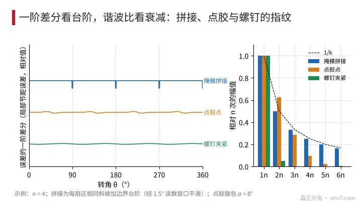
- Sawtooth stitching error with step height h: H_kn = h/(πk), ratios 1 : 1/2 : 1/3 …, a slow power-law decay; the reading window attenuates it only at very high orders.
- Gaussian bump with angular width σ: H_kn ∝ exp(−(k·n·σ)²/2); for n = 4 and σ = 8° the ratios are 1 : 0.63 : 0.29 : 0.10 : 0.02, essentially cut off after the fourth or fifth order.
- Screw sinusoid: the 2n-th order is only a few percent, higher orders negligible.
| Source | H_2n/H_n | H_3n/H_n | 4n and above | Time-domain signature |
|---|---|---|---|---|
| Stitching | about 0.50 | about 0.33 | still significant | steps, spikes in first difference |
| Adhesive dots | 0.3–0.7 | 0.1–0.3 | decays rapidly | smooth bump or S shape |
| Screws | a few percent | about 0 | none | sinusoidal |
(The adhesive-dot row varies with the angular width of the dots; values are examples.) If the sector placement errors are random, stitching also produces a broadband component at all orders, with zeros falling exactly at k·n — another fingerprint of stitching.
Separation procedure
- Compute harmonic ratios: take H_2n/H_n, H_3n/H_n and the residual from 4n upwards. Ratios close to 1/k with no high-order cut-off point first to stitching; only an n-th order points first to screws.
- Look at the first difference: subtracting the errors of adjacent sample points gives the local pitch error. Stitching shows isolated spikes at n equally spaced positions, about as wide as the angular width of the reading window; adhesive dots and screws show only gentle undulation. This step needs dense enough sampling — at least line-by-line measurement near the boundaries.
- Change the mounting angle: re-mount the disc rotated by half a spacing (180°/n) relative to the hub, using a hub mark as phase reference. The stitching component, which follows the disc, reverses its n-th order phase; the screw component, which follows the hub, is unchanged; adhesive dots applied at fixed positions on the hub also follow the hub. Half the difference of the two phasors is the part following the disc, half the sum the part following the hub.
- Re-measure with stress relieved: loosen the screws to half the rated torque and measure again — the screw component changes roughly in proportion to torque; change the temperature — the thermal-stress component of the adhesive dots changes with the temperature difference; the stitching component is unchanged in both cases.
- Check against the layout: find the angles of the stitching boundaries from the photomask layout and compare them with the spike positions. At r = 20 mm, 1″ corresponds to only 0.1 μm of tangential misplacement, hard to resolve by imaging measurement, so the check is usually made with dense angle measurement by the encoder itself.
Engineering takeaways
- For n equally spaced undulations, compute harmonic ratios first: slow 1/k decay points to stitching, cut-off after the fourth or fifth order to local bumps, only the n-th order to clamping.
- Isolated spikes in the first difference are the most direct evidence of stitching steps; the spike width is about the angular width of the reading window.
- Re-mounting rotated by half a spacing separates the components following the disc and the hub, and is more targeted than repeated dismounting.
- n-lobe screw waviness becomes angular error through surface-fibre displacement, about t·n·W/(2r²); 1 μm of waviness can already reach the arcsecond level.
- The stitching component does not change with torque or temperature, so a compensation table stays valid long-term; the adhesive-dot component changes with temperature, so assess the temperature range before compensating.
- In design, make the screw count, adhesive-dot count and mask sector count all different, so that problems can be separated by order.
Summary
For n equally spaced undulations in the error curve, the shape is the clue: stitching gives steps, harmonics falling as 1/k and spikes in the first difference; adhesive dots give smooth bumps with harmonics cut off fairly quickly; screws are nearly sinusoidal, dominated by the n-th order. Make a first judgement from harmonic ratios and the first difference, then confirm by re-mounting rotated by half a spacing and by stress-relief re-measurement, and the problem can be assigned to the mask, bonding or clamping process.
Translated from the ENC7 Chinese technical library (article 0237). Read the Chinese original. Need a disc built to your drawing? Request a quote or see our custom encoder discs.
© Langfang Jingzheng Optoelectronic Technology Co., Ltd. All rights reserved. This article was created with AI assistance.